Ductile Cast Iron

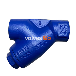
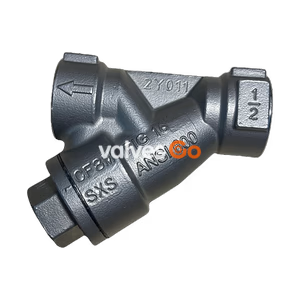
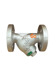
Armstrong A Series Class 250 cast iron Y-type strainers feature a leak-proof screen chamber, straight thread retainer, and multiple screen options for reliable filtration.
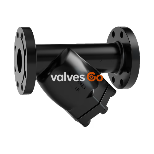
The Armstrong A Series Class 250 Cast Iron Y-Type Strainer is designed to mechanically remove solids from a flowing fluid or gas in a pipeline by utilizing a perforated or mesh straining element. To ensure against untimely shutdown of equipment, these strainers should be installed ahead of pumps, loading valves, control valves, meters, steam traps, turbines, compressors, solenoid valves, nozzles, pressure regulators, burners, unit heaters, and other sensitive equipment.
The A Series features a leak-proof, crush-proof screen chamber. The chamber ends are precision machined, meaning the seating surfaces are perfectly round and smooth, and the chamber length is fixed. Because the screen fits snugly against machined surfaces, particles larger than the screen openings cannot bypass the ends. The straight thread screen retainer allows for tight sealing with less torque through proper gasket compression, reducing the risk of "freezing" compared to hard-to-remove tapered pipe threads.
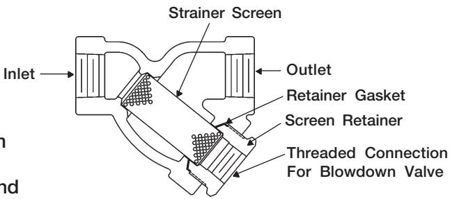
Clean all threaded areas of the pipe thoroughly before installing the strainer. Use pipe dope or teflon tape sparingly. Leave the end thread exposed to avoid introducing the sealant into the piping system. The strainer can be installed in the horizontal or vertical down position.
CAUTION
When installing socket weld strainers 1-1/4" size and larger, and all D-Series strainers, be aware the strainer has a non-metal gasket that can be damaged by excessive heat. Try to minimize welding time, and cool the strainer after welding. If pre- and post-weld heating is needed, removing the gasket may be advisable.
After the initial operation of the system, the strainer should be blown down to remove any installation debris caught in the screen. Repeat the blowdown procedure on a regular schedule thereafter. Frequency of blowdown depends on the operating conditions to which the strainer is subjected.
If no blowdown valve is to be used, the strainer can be cleaned by removing the screen retainer and screen.
WARNING
Always isolate the strainer from the pressurized system before opening to clean. Equipment may be under pressure and operating temperatures can exceed 100°C (212°F). Make sure the strainer is cold before handling! Use a new gasket when reassembling the strainer.
TIP
The strainer screen should be inspected one to two times per year. Recommended spare parts are one screen and three gaskets per strainer.
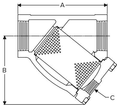
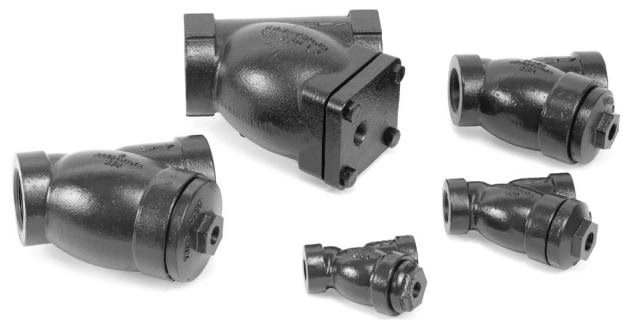
| Connections Size (in) | Body | Standard Screen | Screen Retainer | Gasket | Bolting |
|---|---|---|---|---|---|
| 1/2, 3/4 | ASTM A48 Class 30 Cast Iron | 304 SS .045" perforated | ASTM A48 Class 30 Cast Iron | Spiral Wound | N/A |
| 1, 1-1/2, 2 | ASTM A48 Class 30 Cast Iron | 304 SS .045" perforated | ASTM A48 Class 30 Cast Iron | Spiral Wound | N/A |
| 1-1/4 | ASTM A48 Class 30 Cast Iron | 304 SS .045" perforated | Soft Steel | Spiral Wound | N/A |
| 2-1/2, 3 | ASTM A48 Class 30 Cast Iron | 304 SS .045" perforated | ASTM A48 Class 30 Cast Iron | Non-asbestos | Cap Screws ASTM A193 Gr. B7 |
NOTE: Other screen materials available.
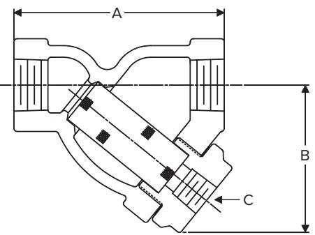
| Size (in) | Ordering Code | Weight (lb) | A (in) | B (in) | C (in) | Max Steam (psig) | Max Water 150°F (psig) | Retainer Type |
|---|---|---|---|---|---|---|---|---|
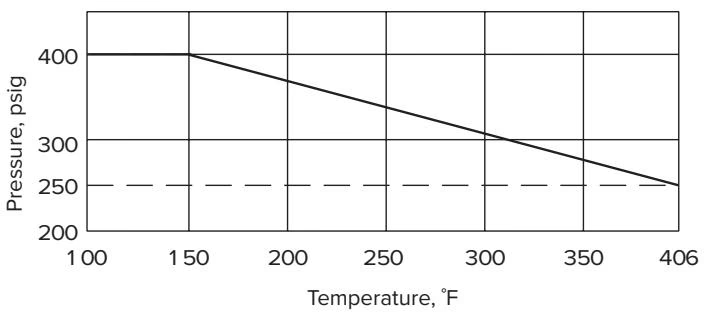
| 1/2 | CA1SC | 3 | 4-1/4 | 3 | 3/8 | 250 | 400 | Threaded |
| 3/4 | CA1SC | 3 | 4-1/4 | 3 | 1/2 | 250 | 400 | Threaded |
| 1 | CA1SC | 4-1/2 | 5 | 3-3/4 | 1/2 | 250 | 400 | Threaded |
| 1-1/4 | CA1SC | 7 | 5-1/2 | 3-7/8 | 1/2 | 250 | 400 | Threaded |
| 1-1/2 | CA1SC | 10 | 6-5/16 | 4-7/16 | 1/2 | 250 | 400 | Threaded |
| 2 | CA1SC | 15 | 7-1/2 | 5-7/16 | 1/2 | 250 | 400 | Threaded |
| 2-1/2 | A1SC | 24-1/2 | 8-1/2 | 6-7/16 | 3/4 | 250 | 400 | Bolted |
| 3 | A1SC | 45-1/2 | 10-1/2 | 8 | 1-1/4 | 250 | 400 | Bolted |
To order replacement strainer screens, state connection size of strainer, screen material and type of perforation or mesh. When ordering replacement screens for flanged strainers, state flange rating.
| Strainer Size (in) | Cast Iron "A" Part No. |
|---|---|
| 3/8" | A4469 |
| 1/2" | A4469 |
| 3/4" | A4470 |
| 1" | A4471 |
| 1-1/4" | A6256 |
| 1-1/2" | A6267B |
| 2" | A6263 |
| 2-1/2" | A21274-1 |
| 3" | A21340-1 |
| 4" | A22106-1 |
| 5" | A21343-1 |
| 6" | A22049-1 |
| 8" | A21427-1 |
| 10" | A21432-1 |
| Strainer Size (in) | Blowdown Plug Part No. | Blowdown Plug Size (in) | Retainer Gasket Part No. |
|---|---|---|---|
| 1/2" | A6002A | 3/8" | A19251 |
| 3/4" | A6003A | 1/2" | A19251 |
| 1" | A6003A | 1/2" | A19252 |
| 1-1/4" | A6003A | 1/2" | A6256 |
| 1-1/2" | A6003A | 1/2" | A19253 |
| 2" | A6003A | 1/2" | A19254 |
Explore similar products in our catalog