

PN16
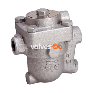
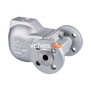
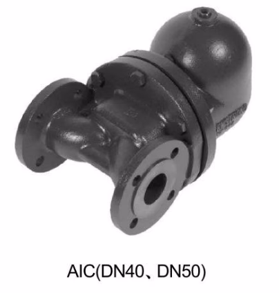
Armstrong AIC/AIC-F/AIC-FH Series Float & Thermostatic Steam Trap features ductile iron body with built-in stainless steel thermostatic air vent, eliminating air binding. Covers DN15-DN50 nominal diameters, supports threaded or flanged connections, horizontal/vertical installation, max differential pressure 3.2MPa, max capacity 28,000kg/h. Suitable for heat exchangers, steam mains, heating equipment from medium-low to high pressure applications. Robust construction, corrosion resistant, field serviceable.
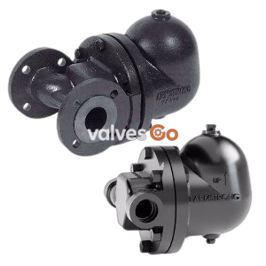
Armstrong AIC/AIC-F/AIC-FH Series Float & Thermostatic Steam Trap is a key device designed for efficient steam system drainage. Its core advantage is the built-in stainless steel thermostatic bellows air vent, which rapidly discharges air and non-condensable gases, completely eliminating air binding and ensuring stable system operation.
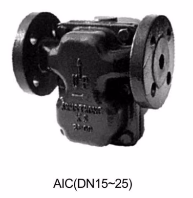
This series is divided into three categories by nominal diameter: AIC DN15-DN25 Series, AIC DN40-DN50 Series, and AIC-FH Integral Flange Series, each suited for different pressure ratings and operating conditions. Internal components are made of stainless steel with enhanced treatment, providing robust construction with excellent corrosion and back pressure resistance for long-term reliable operation under high loads. Field serviceable design reduces maintenance costs.
Suitable for systems requiring continuous drainage and rapid air venting, especially for applications that cannot tolerate pressure fluctuations from intermittent discharge:
Suitable for applications with significant pressure fluctuations or heavy condensate loads:
Suitable for systems requiring continuous drainage, rapid air and non-condensable gas venting, while accommodating pressure fluctuations from intermittent discharge:
| Series | Nominal Diameter | Max Working Pressure | Max Working Differential | Operating Temp |
|---|---|---|---|---|
| AIC | DN15-25 | 1.7MPa @ 232°C | 1.4MPa @ 232°C | 232°C |
| AIC | DN40-50 | 2.5MPa @ 300°C | 3.2MPa @ 300°C | 300°C |
| AIC-FH | - | 4.0MPa @ 300°C | 2.1MPa | 300°C |
| Parameter | Value |
|---|---|
| B (mm) | 6 |
| C (mm) | 28 |
| D (mm) | 17 |
| Max Working Pressure | 1.0MPa |
| Series | Connection Type | Standard | Applicable Sizes |
|---|---|---|---|
| AIC | Threaded | BSPT/NPT | DN15-25, DN40-50 |
| AIC | Flanged | HG20592 PN16 RF | DN15-25 |
| AIC | Flanged | HG20592 PN40 RF | DN40-50 |
| AIC-FH | Integral Flange | ASME B16.5 CL150, HG20592 PN25 | - |
| Component | AIC Series (DN15-25) | AIC Series (DN40-50) | AIC-FH Series |
|---|---|---|---|
| Body, Cover | Ductile Iron ASTM A536 60-40-18 (QT400-18) | Ductile Iron ASTM A395 EN1563 EN-GJS-400-18U 60-40-18 (QT400-18) | Ductile Iron ASTM A536 |
| Disc, Seat | Hardened Chrome Alloy Steel 440 | Hardened Chrome-Moly Steel ASTM A747 Gr.CB 7CV-1, H-90 | Hardened Chrome Alloy Steel 440 |
| Mechanical Internals | 304 Stainless Steel | 304 Stainless Steel | 304 Stainless Steel |
| Float | Stainless Steel | Stainless Steel | Stainless Steel |
| Body/Cover Gasket | Reinforced Graphite | Reinforced Graphite | Reinforced Graphite |
| Air Vent | Nickel-based Alloy Bellows | Nickel-based Alloy Bellows | Nickel-based Alloy Bellows |
| Bolts | Carbon Steel SAE Grade B2 | Carbon Steel ASTM A194 Gr2H | Carbon Steel SAE Grade B2 |
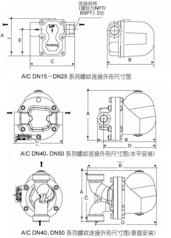
| Installation | DN | A | B | C | D | E |
|---|---|---|---|---|---|---|
| Horizontal | 15 | 135 | 175 | 160 | — | 94.5 |
| Horizontal | 20 | 135 | 175 | 160 | — | 94.5 |
| Horizontal | 25 | 135 | 175 | 160 | — | 94.5 |
| Horizontal | 40 | 278 | 326 | 270 | 289 | — |
| Horizontal | 50 | 278 | 333 | 300 | 289 | — |
| Vertical | 40 | 281 | 386 | 242 | 350 | — |
| Vertical | 50 | 297 | 398 | 275 | 350 | — |
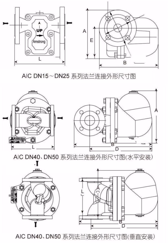
| Installation | DN | A | B | D | E | L (PN16 RF) | L (PN40 RF) | L (PN25 RF) |
|---|---|---|---|---|---|---|---|---|
| Horizontal | 15 | 142 | 175 | — | 96 | 150 | — | — |
| Horizontal | 20 | 147 | 180 | — | 96 | 150 | — | — |
| Horizontal | 25 | 152 | 185 | — | 96 | 160 | — | — |
| Horizontal | 40 | 278 | 411 | 334 | — | — | 230 | 230 |
| Horizontal | 50 | 278 | 420 | 334 | — | — | 230 | 230 |
| Vertical | 40 | 278 | 426 | 350 | — | — | 230 | 230 |
| Vertical | 50 | 278 | 434 | 350 | — | — | 230 | 230 |
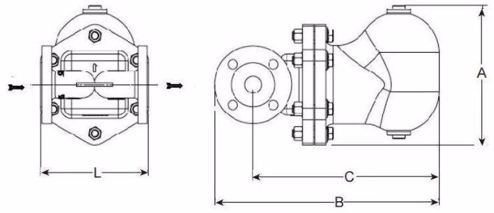
| Installation | DN | A | B | D | L (ASME B16.5 CL150 RF) |
|---|---|---|---|---|---|
| Horizontal | 25 | 201 | 334 | 276 | 160 |
| Installation | DN | Weight |
|---|---|---|
| Horizontal | 15 | 5.2 |
| Horizontal | 20 | 5.3 |
| Horizontal | 25 | 5.4 |
| Horizontal | 40 | 5.1 |
| Horizontal | 50 | 5.1 |
| Vertical | 40 | 32 |
| Vertical | 50 | 32 |
| Installation | DN | Weight |
|---|---|---|
| Horizontal | 15 | 6.15 |
| Horizontal | 20 | 6.55 |
| Horizontal | 25 | 7.3 |
| Horizontal | 40 | 34 |
| Horizontal | 50 | 34 |
| Vertical | 40 | 34 |
| Vertical | 50 | 34 |
| Installation | DN | Weight |
|---|---|---|
| Horizontal | 25 | 13.6 |
Note: For flanged connections other than ASME B16.5 standard, consult supplier for weight information.