PN25

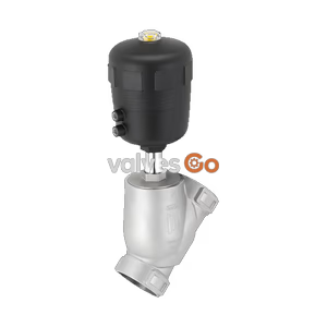
BURKERT 20061791 Type 2920 manually operated 2/2-way angle seat valve. Features 3/4" G internal thread, stainless steel body, PTFE seal, PN 25, and handles media from -10°C to 185°C.
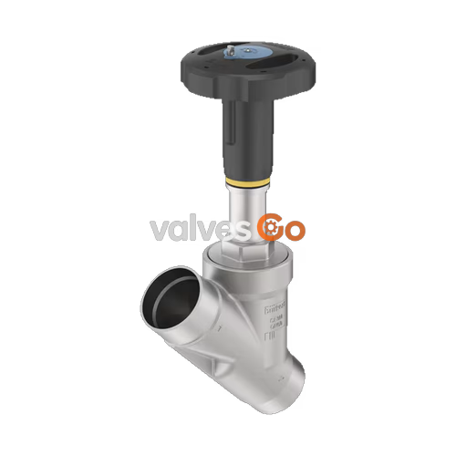
The BURKERT 20061791 Type 2920 is a manually operated 2/2-way angle seat valve designed to control the flow of media. It consists of a manual actuator made of high-quality PPS plastic and a 2-way body made of flow-optimized stainless steel. This specific model features a 3/4" G internal thread connection, a PTFE seat seal, and operates at pressures up to 25 bar (PN 25) and medium temperatures from -10 °C to 185 °C. The tried-and-tested self-adjusting packing gland guarantees optimal tightness and enables low-maintenance operation, even at high switching cycles.
It is suitable for shutting off both neutral and aggressive gaseous and liquid media, including steam, water, alcohols, oils, fuels, hydraulic fluids, salt solutions, alkalis, and organic solvents.
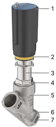
| Item | Description |
|---|---|
| 1 | Handwheel with locking (optional) |
| 2 | Position indicator |
| 3 | Relief bore |
| 4 | Wrench flat for open-end wrench |
| 5 | Angle seat body |
| 6 | Port connection |
| 7 | Flow direction indicator |
| Product properties | Specification |
|---|---|
| Design | Angle seat valve on/off |
| Nominal diameter | DN 20 (3/4") |
| Flow direction | Flow to open (below seat) |
| Operating pressure | 0 bar(g)...25 bar(g) |
| Nominal pressure | PN 25 (DIN EN 1333), Class 150 (DIN EN 1759) |
| Seat leakage | Leakage rate A (DIN EN 12266-1), seat seal PTFE, test medium air |
| Kv value (water) | 11 m³/h |
| Operating medium | Steam, water, neutral gases, alcohols, oils, fuels, hydraulic fluids, salt solutions, alkalis, organic solvents |
| Medium temperature | -10 °C...+185 °C |
| Viscosity | Max. 600 mm²/s |
| Port connection | G (DIN ISO 228-1) Internal thread |
| Ambient temperature | -10 °C...+60 °C |
| Installation position | As required, preferably with actuator upright |
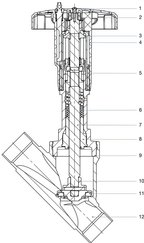
| No. | Element | Material |
|---|---|---|
| 1 | Cover | Polyamide (PA) |
| 2 | Screw | Stainless steel 1.4301 |
| 3 | Lock pin | Stainless steel 1.4305 |
| 4 | Handwheel | Polyphenylene sulfide (PPS) |
| 5 | Optical position indicator with scale | Polyamide (PA) |
| 6 | Packing gland | PTFE V-rings (filled), with spring compensation |
| 7 | Spindle | Stainless steel 1.4401 (316)/1.4404 (316L) |
| 8 | Spindle guide | PEEK |
| 9 | Body seal | Graphite |
| 10 | Swivel plate | Stainless steel 1.4401 (316)/1.4404 (316L) |
| 11 | Seat seal | PTFE |
| 12 | Valve body | Stainless steel 316L/CF3M |
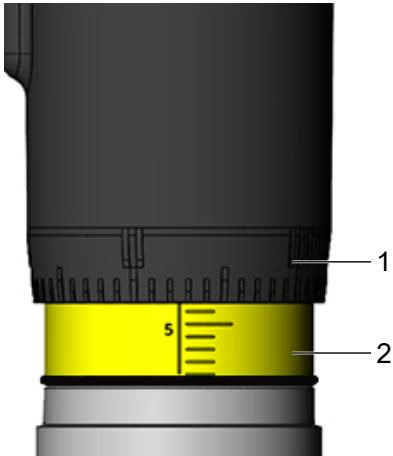
When turning the handwheel anticlockwise, the reproducible stroke scale becomes visible between the position indicator and the handwheel. The scale on the handwheel determines the rotation position of the handwheel (50 positions). The reproducible stroke scale shows, depending on the bottom edge of the handwheel, the relative position of the valve (valve opening) and acts as a fixation point for determining the rotation position.
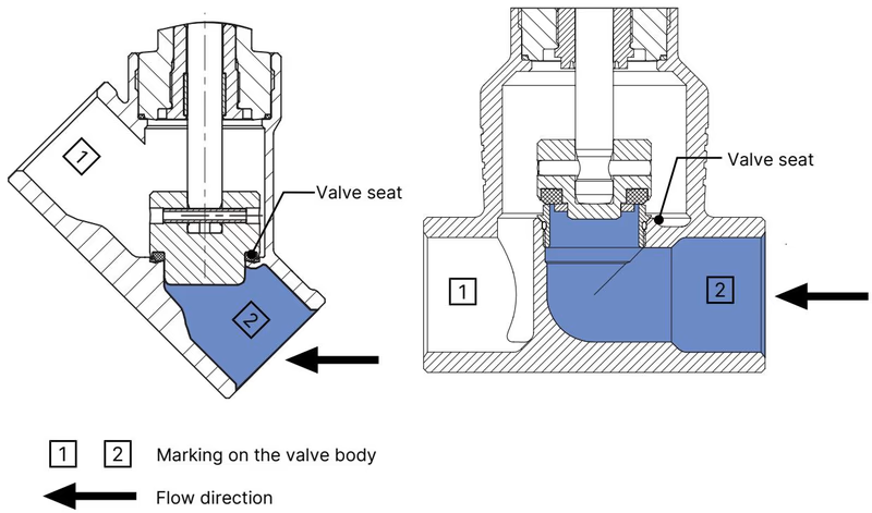
The valve seat is always closed against the medium flow. The flow direction should therefore be set such that the valve reaches the flow beneath the valve seat.
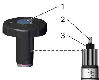
Both the minimum and the maximum position of the valve can be adjusted via an adjustment sleeve. The handwheel can be removed for this purpose.
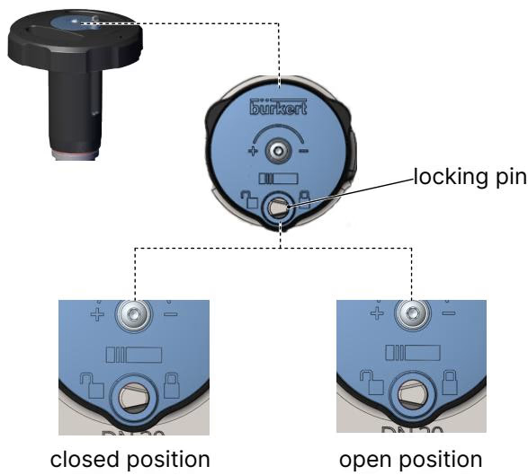
The valve can be secured against unintentional or unauthorized operation. For this purpose, a securing pin can be pressed down and turned. The locking pin has a hole (Ø 3.8) and can be secured with a padlock.
WARNING
The leakage class specified in the technical data cannot be guaranteed when the valve is locked in the closed position, depending on the operating and application conditions.
DANGER
Risk of injury due to high pressure and escaping medium Switch off the pressure before working on the device or system. Vent or drain the lines.
Notes for correct installation:
Inspection intervals:
Explore similar products in our catalog