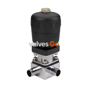
Type 2032

BURKERT 20127850 (Type 2933) 2/2-way manual diaphragm valve. Features DN 15 welded connection, investment cast 316L body, PTFE/EPDM diaphragm, and 0-10 bar pressure range.
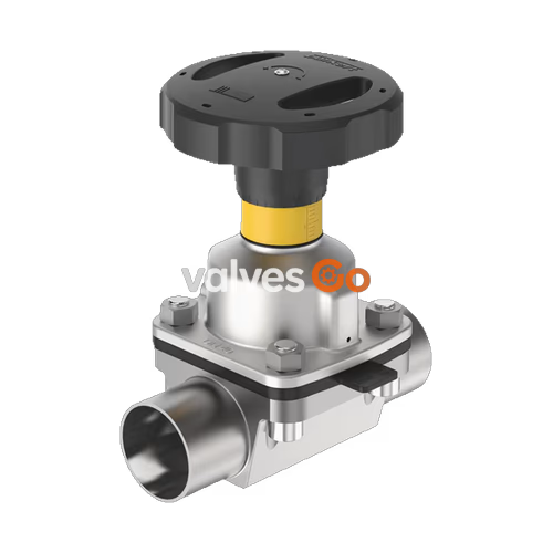
BURKERT 20127850 (Type 2933) is a 2/2-way manually operated diaphragm valve designed for hygienic and aggressive ambient conditions. This specific configuration features a DN 15 welded connection, an investment cast 316L/1.4435 stainless steel valve body, and a PTFE diaphragm with an EPDM backing membrane. The manual actuator is equipped with a stainless steel handwheel, an integrated visual position indicator with a scale, and a single minimum-stroke limiter (closing limiter). The flow-optimised valve body with minimum dead space enables high flow values and reliable operation at pressures up to 10 bar and temperatures up to 130 °C.
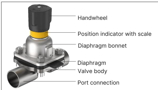
The 20127850 diaphragm valve complies with stringent industry standards for food, beverage, and pharmaceutical applications:
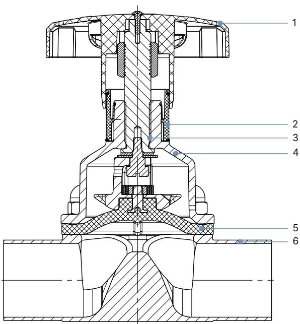
| No. | Element | Material |
|---|---|---|
| 1 | Handwheel | Stainless steel (specific to SKU 20127850) |
| 2 | Visual position indicator | Polyamide (PA), Stainless steel 1.4305 |
| 3 | Valve spindle | Stainless steel 1.4305 |
| 4 | Diaphragm bonnet | Stainless steel (specific to SKU 20127850) |
| 5 | Diaphragm | PTFE with EPDM backing membrane (EA) |
| 6 | Valve body | Investment cast material 316L/1.4435 (VG) |
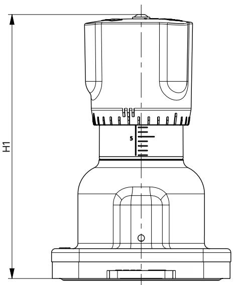
| Diaphragm size | H1 (mm) | H2 (mm) | Ø B (mm) |
|---|---|---|---|
| 15 | 84 | 78 | 45 |
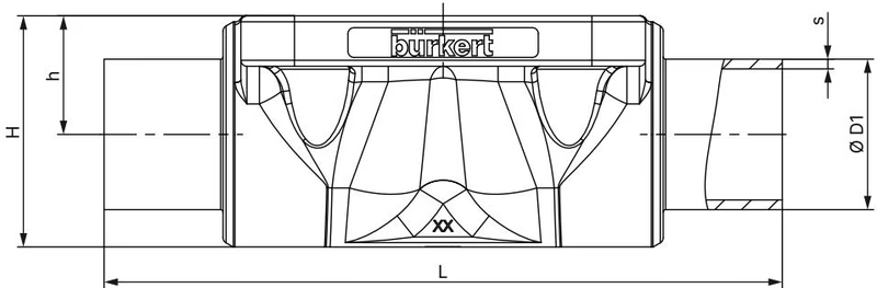
| Diaphragm size | Port connection DN | ØD1 (mm) | s (mm) | L (mm) | h (mm) | H (mm) |
|---|---|---|---|---|---|---|
| 15 | 15 | 21.3 | 1.6 | 110 | 13.5 | 25.0 |
Note: Dimensions correspond to DIN EN ISO 1127 / ISO 4200 / DIN 11866 series B.
Flow Characteristics
| Diaphragm size | Maximum static operating pressure | Tightening torque for PTFE/EPDM |
|---|---|---|
| 15 | 10 bar | 1.7 Nm |
WARNING
The tightening torques refer to the static media pressures specified above. Excessive torque can shorten the service life of the diaphragm. A tolerance of +10% applies to the tightening torques specified.

It is the responsibility of the installer and the operator to ensure self-draining. Observe the rules for self-draining during installation:
When installing the actuator onto the valve body, tighten each fastening screw in 3 stages (approx. 1/3, approx. 2/3, 3/3 of the tightening torque) crosswise. The diaphragm should be positioned and pressed evenly around the actuator and valve body.
Explore similar products in our catalog