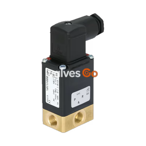
PN16

BURKERT 20129237 Type 8652 AirLINE valve island for process automation. Features 8 valve ports, Industrial Ethernet, -1 to 10 bar pressure range, and IP20 protection.
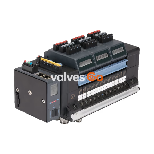
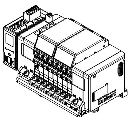
The BURKERT 20129237 Type 8652 AirLINE valve island has been especially developed for process automation requirements. New diagnostic functions can be visualised on the LC display, both in clear text as well as symbols. This makes it easy to relate to the shown messages and helps to save time during start-up and maintenance. Furthermore, the diagnostic message is also available at the controller, enabling a fast overview of the plant status. The hardware is optimised for installation at the bottom of the control cabinet, though installation on a standard rail is also possible. Key pneumatic functions ensure increased process reliability, such as check valves in the exhaust air ducts that prevent unplanned actuation due to pressure peaks.
Features include safety-related shut-off of valves, higher plant availability with PROFINET S2 (system redundancy), and EX-variants (ATEX / IECEx Zone 2, CCC, cURus HazLoc CL I, II, III Div 2).
| Attribute | Value |
|---|---|
| Number of valve ports | 8 PCE |
| Valve positions 1-7 | 5/2-way monostable WWH |
| Valve position 8 | Blind plate |
| Pressure port | D10 (Brass) |
| Working port | D6 (Brass) |
| AirLINE Quick material | Aluminium |
| Protocol | Industrial EtherNet (PROFINET IO, EtherNet IP, Modbus TCP, EtherCAT, CC-Link IE Field Basic) |
| Digital inputs number | 16 |
| Protection type | IP20 |
| Property | Value |
|---|---|
| Body Material | PA (polyamide) |
| Seal Material | NBR and PUR |
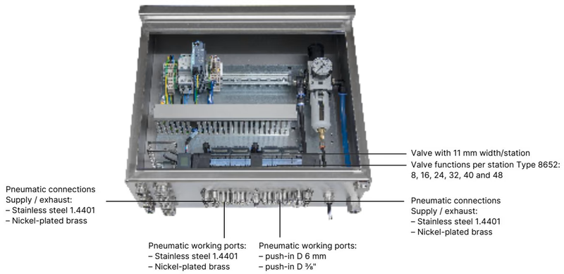
| Width per station | 11 mm |
| Number of valve slots | Max. 24 |
| Maximum number of valve functions | Max. 48 |
| Pressure range | Vac...10 bar |
| External supply air | 3...10 bar |
| Flow rate QNn value air | 310 l/min (measured at +20 °C, 6 bar pressure at valve inlet and 1 bar differential pressure) |
| Operating voltage | 24 V DC (±10% tolerance) |
| Nominal power of each valve | 0.7 W (0.175 W after power reduction) |
| Operating medium | Oil-free or lubricated compressed dry air, neutral gases (5 μm filter recommended) |
| Ambient temperature | -10 °C...+55 °C |
AirLINE Quick considerably reduces the use of components in the control cabinet. With the AirLINE Quick Adapter, the valve terminal is adapted directly to the control cabinet floor or control cabinet wall.
Advantages:
| Circuit function | Description |
|---|---|
| C (CF C) | 3/2-way solenoid valve, Servo-controlled, with manual override, Normally closed |
| C (CF C) | 2 × 3/2-way solenoid valve, Servo-controlled, with manual override, Normally closed |
| D (CF D) | 2 × 3/2-way solenoid valve, Servo-controlled, with manual override, Normally open |
| H (CF H) | 5/2-way solenoid valve, Servo-controlled, with manual override. Pressure applied via port (1), therefore one of the two ports (2) or (4) is under pressure. |
| L (CF L) | 5/3-way solenoid valve, With manual override, In middle position all ports locked |
| M (CF M) | 5/3-way solenoid valve, Servo-controlled, with manual override, In middle position ports 2 and 4 ventilated |
| N (CF N) | 5/3-way solenoid valve, With manual override, In middle position ports 2 and 4 exhausted |
| Z (CF Z) | 5/2-way solenoid valve, Impulse variant with 2 coils and manual override. Pressure applied via port (1), therefore one of the two ports (2) or (4) is under pressure. |
| Variant | A | B | C | m | n |
|---|---|---|---|---|---|
| 4-fold | 66 | - | 4 x M5 | 3 | 1 |
| 8-fold | 35 | 111 | 8 x M5 | 7 | 2 |
| 12-fold | 77 | 154 | 10 x M5 | 11 | 3 |
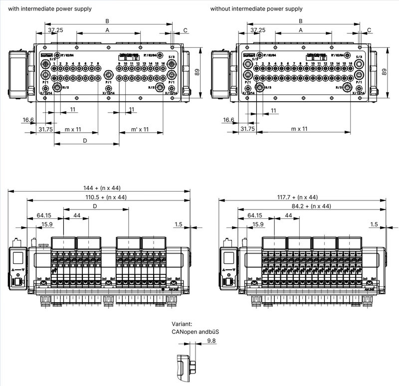
| Variant | A | B | C | D | m | m' | n |
|---|---|---|---|---|---|---|---|
| 16-fold with intermediate supply | 112 | 224 | 10 x M5 | 114.3 | 7 | 7 | 4 |
| 20-fold with intermediate supply | 134 | 268 | 10 x M5 | 158.3 | 11 | 7 | 5 |
| 24-fold with intermediate supply | 156 | 312 | 10 x M5 | 158.3 | 11 | 11 | 6 |
| 16-fold without intermediate supply | 99 | 198 | 10 x M5 | - | 15 | - | 4 |
| 20-fold without intermediate supply | 121 | 242 | 10 x M5 | - | 19 | - | 5 |
| 24-fold without intermediate supply | 143 | 286 | 10 x M5 | - | 23 | - | 6 |
| Spring-loaded terminal 5-pin | Colour | Assignment |
|---|---|---|
| 1 | Red | 24 V DC |
| 2 | White | CAN_H (büS connection) |
| 3 | Green | SHIELDING |
| 4 | Blue | CAN_L (büS connection) |
| 5 | Black | GND |
| Spring-loaded terminal 2-pin | Colour | Assignment |
|---|---|---|
| 1 | Red | AUX 24 V |
| 2 | Black | GND |
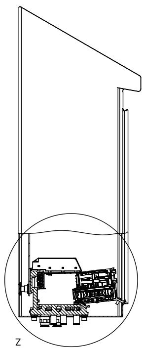
To use the Hot Swap function, always observe a minimum distance to the front edge of the control cabinet when installing the valve island inside the control cabinet.
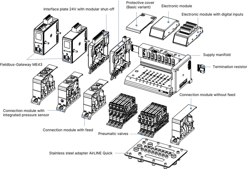
The digital inputs are supplied (24 V) by the electronic module. Current is limited to maximum 30 mA per digital input. Standard 3-wire sensors and 2-wire sensors with voltages between 10…30 V as well as mechanical limit switches can be used.
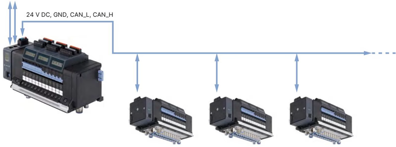
The illustration shows a network with the example of AirLINE Type 8652 with Industrial Ethernet variant as master valve terminal and various AirLINE Type 8652 with büS variant as slave valve terminals.
Safety Instructions for EX Areas
Explore similar products in our catalog