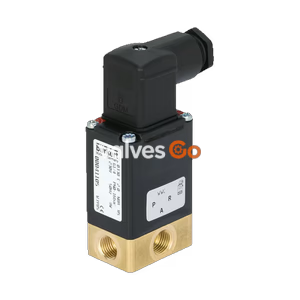
PN16

BURKERT 20140087 Type 8640 modular valve island. 19mm width per station, 12-bank, 3/2 valve function, 2-8 bar, collective socket module, IP20.
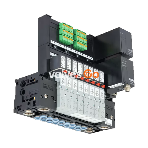
The BURKERT 20140087 Type 8640 valve unit system is designed to solve diverse and complex control problems due to its systematic modular construction and combination of pneumatic and electrical interfaces. By putting together a row of pneumatic modules with different numbers of valves, 2 to 24 valve functionalities may be realized on one valve unit. Electrical connectivity is achieved by either fieldbus interfaces, common connection (parallel connection technique) or multipin interfaces.

The valves allow different applications to be covered. Bodies and connection modules are made of high-quality plastic (polyamide) and are easy to assemble by means of the built-in snap connectors. The 19mm width per station variant utilizes Type 5470 solenoid valves.
| Feature | Specification (Type 5470 / 19mm) |
|---|---|
| Body Material | PA (polyamide) |
| Seal Material | NBR |
| Width per station | 19 mm |
| Manual override | Standard |
| Number of valve slots | Max. 24 |
| Pressure range | Vac. 2...10 bar (Overpressure to atmospheric pressure) |
| Flow rate QNn value air | 300 l/min measured at +20 °C, 6 bar pressure at valve inlet and 1 bar differential pressure |
| Nominal operating mode | Continuous operation (100% duty cycle) |
| Operating voltage | 24 V DC (±10% tolerance) |
| Nominal power of each valve | 1 W, 2 W, 3 W |
| Operating medium | Oil-free or lubricated compressed dry air, neutral gases (5 μm filter recommended) |
| Degree of protection | IP20 / IP65 in closed control cabinets |
| Ambient temperature | 10 °C...+ 55 °C |
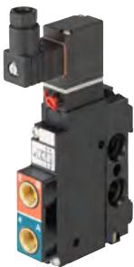
The solenoid valve Type 5470 consists of a pneumatic valve body fitted with a Type 6106 rocker pilot valve. An armature with a tilting bearing, similar to a rocker, tilts within the body of the pilot valve, and switches the valve. The minimal tilting movement of the rocker is non-wearing, and basic lubrication is unnecessary.
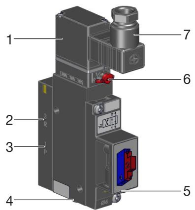
Structure of solenoid valve type 5470:
Manual Override
To operate the valve manually, press the manual override and turn it 90° clockwise (until it stops). The manual override is locked and does not reset automatically. Only operate the manual override when the power is off.
| Symbol | Description |
|---|---|
| C (CF C) | 3/2-way solenoid valve. Servo-controlled, with manual override. Normally closed. |
| D (CF D) | 3/2-way solenoid valve. Servo-controlled, with manual override. Normally open. |
| G (CF G) | 4/2-way solenoid valve. Servo-controlled. |
Collective connection modules and multipole modules:
Fieldbus modules:
WARNING
Risk of injury due to high pressure and escaping medium. Switch off the pressure before working on the device or system. Vent or drain the pipes.
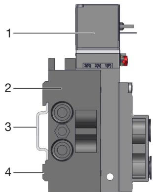
Standard rail installation:
Wall installation: Fasten the valve block directly to the wall with M4 screws.
Before connection, check the hose lines for contamination and clean them. If necessary, install dirt traps upstream of the valve inlet (≤ 5 µm).
INFO
Requirements for hose lines:
DANGER
Risk of injury due to electric shock. Switch off voltage before working on the device or system. Secure against reactivation. When screwing in the solenoid with the cable plug, make sure that the seal is properly seated.
Screw on the cable plug observing the maximum tightening torque of 0.3 Nm. Check that the seal is correctly fitted. Connect the protective conductor and check electrical continuity between coil and housing.
Explore similar products in our catalog