
Skip to content
Built-in Steam TrapMechanical PumpHigh Pressure

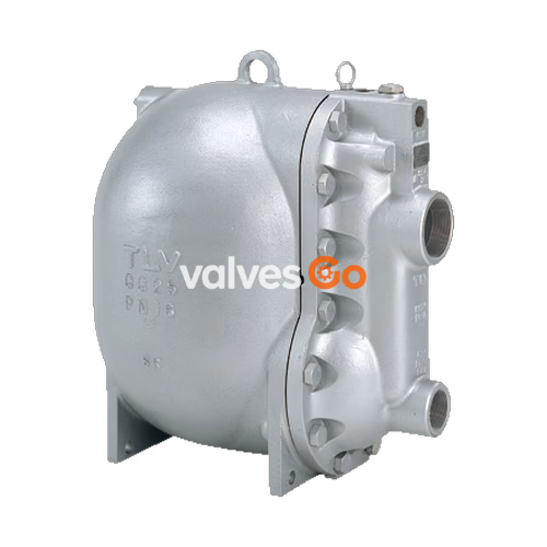
TLV GT14 PowerTrap Automatic Pump Trap

TLV GT14 PowerTrap mechanical pump with built-in steam trap. Discharges condensate from low to high pressure. Max motive pressure 1.4 MPaG.
TLV GT14 PowerTrap Automatic Pump Trap

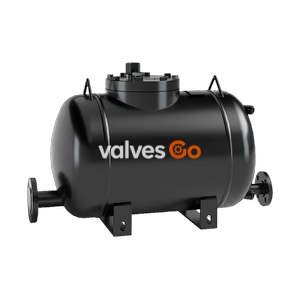
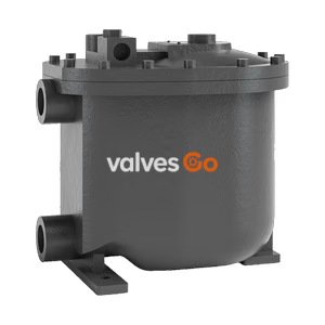
The TLV GT14 PowerTrap is a mechanical pump with a built-in steam trap function, designed to discharge liquid from vacuum-pressure or low-pressure areas to high-pressure areas, or from lower to higher elevations. The GT model is suitable for applications where the inlet pressure may alternately be lower than or higher than the outlet pressure. The GT14 and GP14 models are specifically designed for higher-pressure systems. Pumped fluids are generally limited to steam condensate and water.

Application Systems

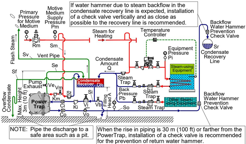
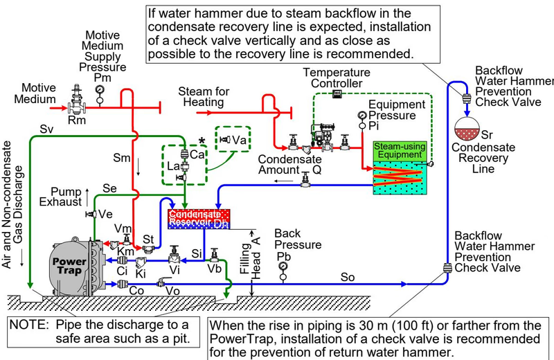
There are two primary types of delivery systems for the PowerTrap: Closed Systems and Open Systems.

Type of SystemClosed SystemOpen System
BenefitsNo need for an external steam trap (GT model features built-in trap). No flash steam discharge. Smaller reservoir required. Can be used with vacuum equipment.Can collect condensate from multiple pieces of equipment. Can be used where the trap is lower than the receiver.
NotesOnly one piece of equipment is possible per system. The equipment has a minimum height requirement to ensure condensate flows naturally by gravity (approx. 1 m).A separate steam trap is required for each piece of equipment.
ModelMechanical pump with built-in trap (GT10/GT14). Mechanical pump (GP10/GP14) where there is ALWAYS a negative pressure differential.Mechanical pump (GP10/GP14)

Operation

WARNING

Take measures to prevent people from coming into direct contact with product outlets. Failure to do so may result in burns or other injury from the discharge of fluids.
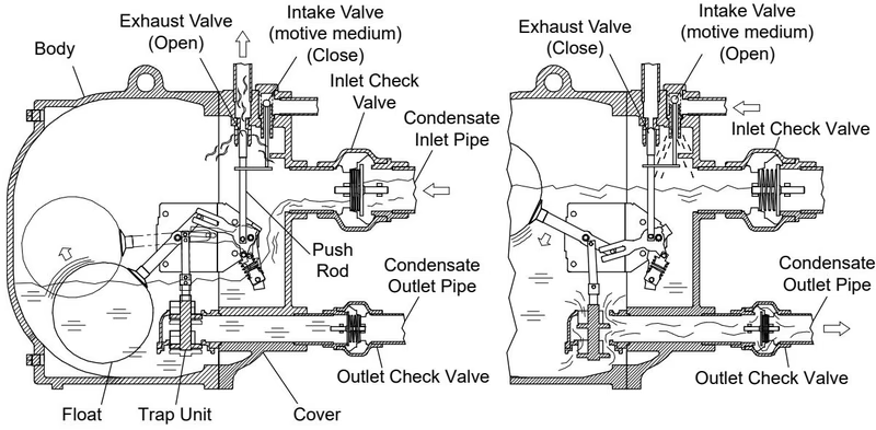
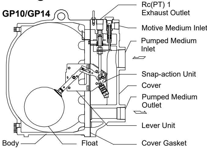
  1. Condensate Inflow: When condensate flows from the condensate inlet pipe through the inlet check valve into the body of the unit, the air in the body escapes through the exhaust valve, and the float rises. For the GT model, the main valve on the trap unit opens as the float rises. When equipment pressure is greater than back pressure, condensate passes through the outlet check valve and is discharged. When equipment pressure is less than or equal to back pressure, condensate collects in the body.
  2. Condensate Discharge: When the float rises to its high level, the push rod on the snap-action unit rises quickly, simultaneously closing the exhaust valve and opening the intake (motive medium) valve. The motive medium pressure causes the internal pressure to become greater than the back pressure. The inlet check valve closes, the outlet check valve opens, and condensate is discharged.
  3. As condensate is discharged, the water level drops and the float descends. Reaching its low level, the push rod moves down quickly, opening the exhaust valve and closing the intake valve, reverting to the inflow status.

TLV GT14 operation stages

Specifications

DANGER

Install properly and DO NOT use this product outside the recommended operating pressure, temperature and other specification ranges. Improper use may result in hazards such as damage to the product or malfunctions leading to serious accidents.
  • Motive Medium Pressure Range (GP14/GT14): 0.03 to 1.4 MPaG (0.3 to 14 barg / 5 to 200 psig)
  • Maximum Allowable Back Pressure: 0.05 MPa (0.5 bar / 7 psi) less than the motive medium pressure used (but not to exceed 1.05 MPaG for GP14/GT14).
  • Motive Medium:
    • Open Systems: Steam, compressed air, or nitrogen.
    • Closed Systems: Steam.

TLV GT14 nameplate specifications

Configuration

TLV GT14 configuration overview

Installation and Piping

Motive Medium Supply Piping

  • The motive medium supply pipe diameter should be at least 20 mm (3/4 in).
  • Install a 40-mesh or finer strainer on the motive medium supply pipe as close to the PowerTrap as possible.
  • If the supply pressure is greater than the maximum operating pressure, install a pressure reducing valve and a safety valve.

Exhaust Piping

  • The exhaust pipe diameter should be at least 25 mm (1 in).
  • The exhaust pipe should be connected to the top of the receiver/reservoir.
  • Ensure the distance from the ground to the highest point on the exhaust pipe does not exceed 3 m (10 ft).

Open System Piping Example

TLV GT14 open system piping example

Closed System Piping Example

TLV GT14 closed system piping example

TIP

In order to ensure proper discharge capacity, use full bore ball valves or gate valves on the pumped medium inlet and outlet lines as well as on the motive medium supply and exhaust lines. Only recommended check valves (CK3MG, CKF3MG) should be used.