


PN16

TLV JH7RM-B cast steel free float steam trap with bimetal thermostatic air venting, suitable for medium-size process equipment, superheated steam, and high-pressure applications up to 65 barg.
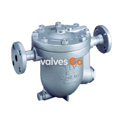
TLV JH7RM-B is a reliable and durable cast steel free float steam trap with thermostatic bimetal air venting. It is designed for use on medium-size process equipment and is suitable for both superheated and high-pressure applications up to 65 barg and 425 °C. The self-modulating free float provides continuous, smooth, low-velocity condensate discharge as process loads vary. A precision-ground float, constant water seal, and three-point seating design ensure a steam-tight seal even under no-load conditions. The built-in thermostatic bimetal air vent valve vents air automatically for rapid startup, and the inline-repairable design simplifies cleaning and reduces maintenance costs.
| Model | JH7RM-B |
|---|---|
| Connection | Socket Welded, Flanged |
| Size | DN 20, 25, 40, 50 |
| Orifice No. | 65 |
| Maximum Operating Pressure (PMO) | 65 barg |
| Maximum Differential Pressure (ΔPMX) | 65 bar |
| Maximum Operating Temperature (TMO) | 425 °C |
| Type of Air Vent | Bimetal (vents air up to approx. 100 °C) |
WARNING
Maximum allowable pressure (PMA) is 65 barg and maximum allowable temperature (TMA) is 425 °C. These are PRESSURE SHELL DESIGN CONDITIONS, NOT OPERATING CONDITIONS. To avoid malfunctions, product damage, accidents, or serious injury, DO NOT use this product outside the specification range.
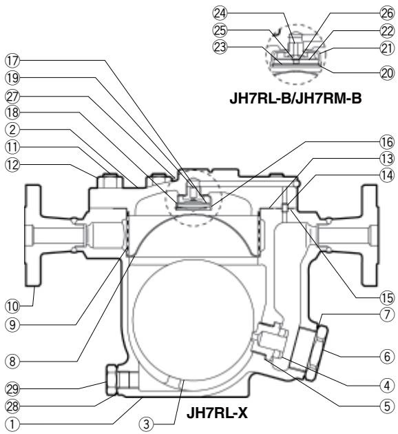
| No. | Description | Material |
|---|---|---|
| 1 | Body | Cast Steel A216 Gr.WCB |
| 2 | Cover | Carbon Steel A105 |
| 3 | Float | Stainless Steel SUS316L |
| 5 | Orifice Gasket | Soft Iron SUYP |
| 6 | Orifice Plug | Cast Stainless Steel A351 Gr.CF8 |
| 7 | Orifice Plug Gasket | Soft Iron SUYP |
| 8 | Screen Holder | Stainless Steel SUS304 |
| 9 | Screen inside/outside | Stainless Steel SUS430/304 |
WARNING
Installation, inspection, maintenance, repairs, disassembly, adjustment, and valve opening/closing should be carried out only by trained maintenance personnel.
To ensure proper piping arrangement:
Operational inspections should be performed at least twice per year, or as called for by trap operating conditions. Steam trap failure may result in temperature drop in the equipment, poor product quality, or losses due to steam leakage.
DANGER
NEVER apply direct heat to the float. The float may explode due to increased internal pressure, causing accidents leading to serious injury or property and equipment damage.
WARNING
Before attempting to open the trap, close the inlet and outlet isolation valves and wait until the trap has cooled completely. Failure to do so may result in burns.
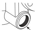
The seal on the threaded plugs/holders is formed by a flat metal gasket. Ensure the gasket is not pinched in the thread recesses during assembly.
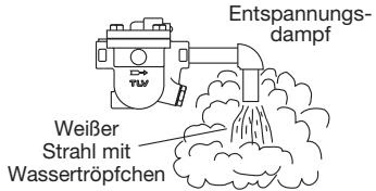
A visual inspection can determine the necessity for immediate maintenance if the trap is open to atmosphere.
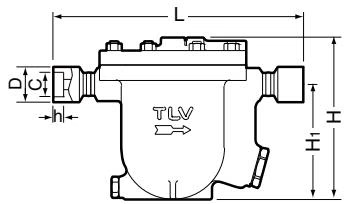
| DN | L (mm) | H (mm) | H1 (mm) | φW (mm) | Weight (kg) |
|---|---|---|---|---|---|
| 20 | 322 | 231 | 160 | 222 | 19 |
| 25 | 334 | 231 | 160 | 222 | 19 |
| 40 | 336 | 231 | 160 | 222 | 21 |
| 50 | 336 | 231 | 160 | 222 | 22 |
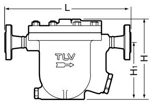
| DN | L (ASME 150/300/600RF) | L (ASME 900RF) | H (mm) | H1 (mm) | φW (mm) | Weight (kg) |
|---|---|---|---|---|---|---|
| 20 | 340 | 370 | 231 | 160 | 222 | 25 |
| 25 | 385 | 395 | 231 | 160 | 222 | 29 |
| 40 | 380 | 390 | 231 | 160 | 222 | 34 |
| 50 | 390 | 400 | 231 | 160 | 222 | 46 |
(Note: Dimensions are based on the JH7RM-B values in parentheses from the source table.)
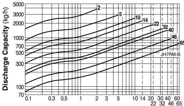
WARNING
DO NOT use traps under conditions that exceed maximum differential pressure, as condensate backup will occur! Recommended safety factor: at least 1.5.




