PN16

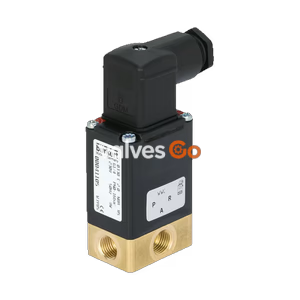
Burkert Type 6014 direct-acting, compact 3/2-way plunger solenoid valve. Features vibration-proof bolted coil system, up to DN 2.5, and explosion-proof variants.
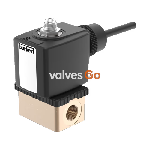
Burkert Type 6014 is a direct-acting plunger valve. The stopper and core guide tube are welded together to enhance pressure resistance and leak-tightness. Various seal material combinations are available depending on the application. A Bürkert-specific flange variant (SFB) enables space-saving arrangement of valves on a manifold. Kick and Drop coils are available for the reduction of electrical power consumption during operation.
| Product properties | |
|---|---|
| Seal | FKM (EPDM on request) |
| Body | Brass, stainless steel 1.4305/303, polyamide (sub-base) |
| Coil | Polyamide (epoxy on request) |
| Manual override | This is an “emergency manual override” which allows manual operation in the event of a fault. (Leakage possible) |
| Orifice | DN 1.5...DN 2.5 |
| Circuit function | C, D and T |
| Thermal insulation class | Polyamide coil class B, Epoxy coil class H |
| Duty cycle | 100% continuous operation. Intermittent operation 60% (30 min) or with 5 W coil (on request) |
| Operating voltage | 24 V DC, 24 V 50 Hz, 24 V 60 Hz, 110 V 50 Hz, 120 V 60 Hz, 230 V 50 Hz, 240 V 60 Hz (other voltages on request) |
| Voltage tolerance | ±10% |
| Operating medium | Technical vacuum, neutral gases and liquids (e.g. compressed air, town gas, natural gas, water, hydraulic oil, petrol) |
| Medium temperature (FKM) | -10 °C...+100 °C (PA coil), -10 °C...+120 °C (epoxy coil), -40 °C on request |
| Viscosity | Max. 21 mm²/s |
| Port connection | G 1/8, G 1/4, NPT 1/8, NPT 1/4, sub-base (SFB) |
| Degree of protection | IP65 with cable plug Type 2518, NEMA 4X with cable plug Type 2509 with stainless steel variants |
| Installation position | As required, preferably with actuator upright |
| Ambient temperature | Max. +55 °C |
UL Approval Operating Conditions
For devices with UL approval (General Purpose Valve):
| Symbol | Description |
|---|---|
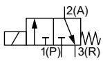 | Circuit function C (CF C) 3/2-way solenoid valve Direct-acting Normally closed |
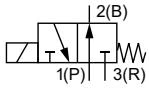 | Circuit function D (CF D) 3/2-way solenoid valve Direct-acting Normally open |
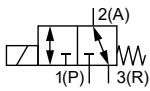 | Circuit function T (CF T) 3/2-way solenoid valve Direct-acting Flow direction optional Normally closed |
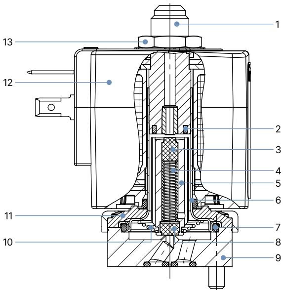
| No. | Element | Material |
|---|---|---|
| 1 | Stopper | Stainless steel 1.4105/430F |
| 2 | Shading ring | Cu (brass variant), Ag (stainless steel variant) |
| 3 | Plunger seal | FKM |
| 4 | Spring | Stainless steel 1.4310/301 |
| 5 | Magnetic core | Stainless steel 1.4105/430F |
| 6 | Core guide tube | Stainless steel 1.4303/305/308 |
| 7 | O-ring | FKM |
| 8 | Plunger seal | FKM |
| 9 | Valve body | Brass, Stainless steel 1.4305/303, Stainless steel 1.4401/316 |
| 10 | Spring | Stainless steel 1.4310/301 |
| 11 | Sub-base | Steel, surface finish thick-film passivated (brass variant), Stainless steel 1.4301/304 (stainless steel variant) |
| 12 | Coil | PA (Polyamide), Epoxy (High temperature variant) |
| 13 | Nut | Steel, surface finish thick-film passivated (brass variant), Stainless steel 1.4305/303 PTFE coated (stainless steel variant) |
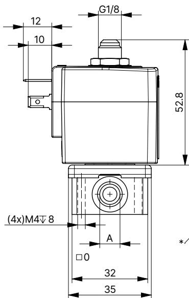
| Port connection | A [inch] | B [mm] | C [mm] | D [mm] | G [mm] |
|---|---|---|---|---|---|
| Threaded without manual override | G 1/8 | 32 | 20.8 | 32.6 | 8 |
| Threaded without manual override | G 1/4 | 46 | 26.8 | 49 | 12 |
| Threaded with manual override | G 1/8 | 32 | 20.8 | 32.6 | 8 |
| Threaded with manual override | G 1/4 | 46 | 26.8 | 49 | 12 |
| Sub-base | - | 32 | 14.3 | 32.6 | - |
| Orifice [mm] | Coil power [W] | Inrush AC [VA] | Hold AC [VA/W] | Opening [ms] | Closing [ms] |
|---|---|---|---|---|---|
| 1.5 | 8 W AC or 8 W DC (9) | 24 | 8 | 10...15 | 15...20 |
| 2.0 | 8 W AC or 8 W DC (9) | 24 | 8 | 10...15 | 15...20 |
| 2.5 | 8 W AC or 8 W DC (9) | 24 | 8 | 15...20 | 10...22 |
(Measurement at +20 °C, 6 bar at the valve outlet, opening: pressure build-up 0…90 %, closing: pressure reduction 100…10 %)
The valves are equipped with different springs for specific circuit functions. When used with other circuit functions, the permissible operating pressure changes according to the following table.
| DN | Circuit function | Max. operating pressure [bar] for A | B | C | D | T |
|---|---|---|---|---|---|---|
| 1.5 | C | 16 | 22 | 16 | 2 | 2 |
| 1.5 | D | 2 | 2.5 | 2 | 16 | 2 |
| 1.5 | T | 10 | 16 | 10 | 6 | 6 |
| 2.0 | C | 10 | 14 | 10 | 1 | 1 |
| 2.0 | D | 1 | 1.5 | 1 | 10 | 1 |
| 2.0 | T | 6 | 10 | 6 | 4 | 4 |
| 2.5 | C | 6 | 9 | 6 | 0.7 | 0.7 |
| 2.5 | D | 0.7 | 1 | 0.7 | 6 | 0.7 |
| 2.5 | T | 3.5 | 6 | 3.5 | 2.5 | 2.5 |
Explore similar products in our catalog