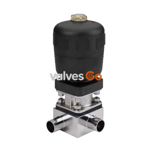
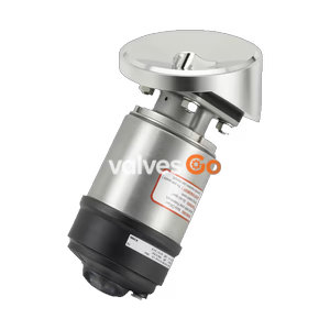
Type 2032

Burkert 20142575 (Type 2933) 2/2-way manual diaphragm valve. Features DN 8 welded connection, forged stainless steel 316L body, and PTFE/EPDM diaphragm. ATEX/IECEx approved for 0-10 bar and -10 to 130°C.
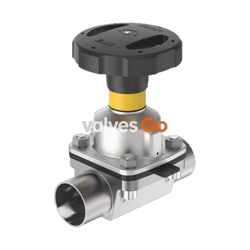
Burkert 20142575 (Type 2933) is a 2/2-way diaphragm valve with a manually operated actuator. The manual actuator with a plastic handwheel (PPS) features a stainless steel diaphragm bonnet, ensuring suitability for hygienic or aggressive ambient conditions. The flow-optimised forged stainless steel 316L (1.4435 BN2) valve body with minimum dead space enables high flow values. This specific model features a DN 8 (NPS 1/4) welded connection (ASME BPE / DIN 11866 Series C) and a PTFE with EPDM backing membrane, supporting medium temperatures from -10 °C to +130 °C and pressures up to 10 bar.
The actuator has a compact, autoclavable design. It is equipped with an integrated visual position indicator and a single min-stroke limiter (closing limiter). This explosion-proof ATEX/IECEx device variant is suitable for demanding environments.
INFO
The product complies with the following approvals and conformities.
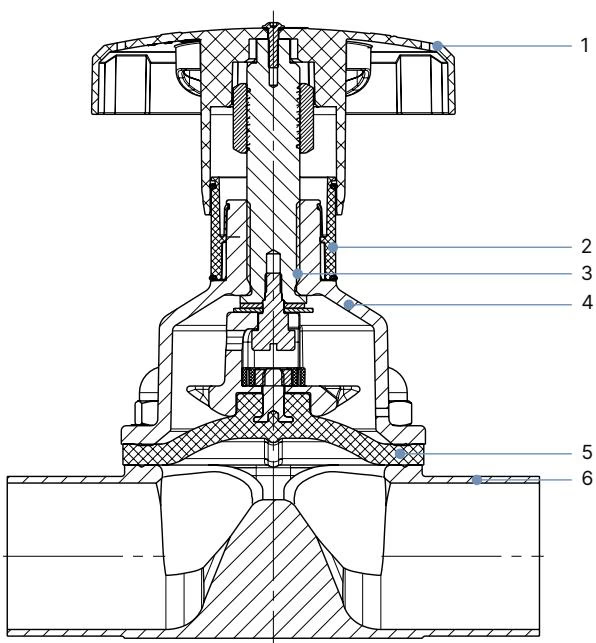
| No. | Element | Material |
|---|---|---|
| 1 | Handwheel | Polyphenylene sulphide (PPS) |
| 2 | Visual position indicator | Polyamide (PA), Stainless steel 1.4305 |
| 3 | Valve spindle | Stainless steel 1.4305 |
| 4 | Diaphragm bonnet | Stainless steel |
| 5 | Diaphragm | PTFE with EPDM backing membrane |
| 6 | Valve body | Forged stainless steel 316L/1.4435 BN2 |
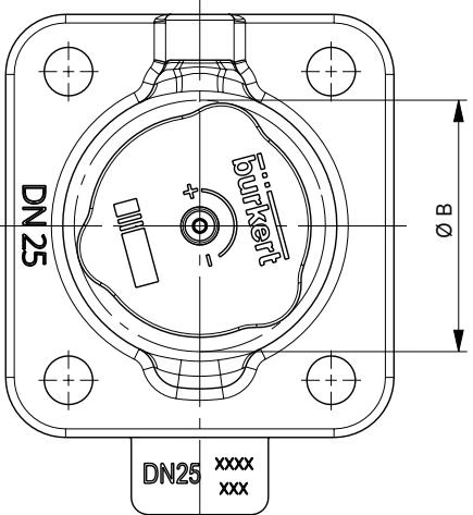
| Diaphragm size | H1 | H2 | ∅ B |
|---|---|---|---|
| 8 | 54 | 49 | 35 |
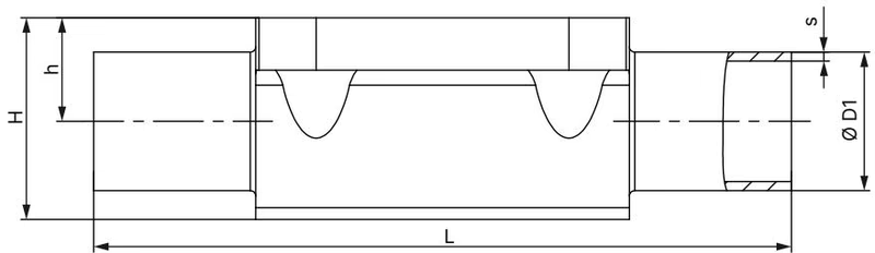
ASME BPE / DIN 11866 Series C
| Diaphragm size | Port connection DN | ∅D1 | s | L | h | H |
|---|---|---|---|---|---|---|
| 8 | 1/4" | 6.35 | 0.89 | 78 | 5.7 | 15.2 |
WARNING
The following tightening torques refer to the static media pressures specified above. Excessive torque can shorten the service life of the diaphragm.
| Diaphragm size | Medium pressure [bar] | Static Tightening Torque (PTFE) [Nm] | Dynamic Tightening Torque (PTFE) [Nm] |
|---|---|---|---|
| 8 | 10 | 1.1 | 1.2 |
DANGER
Risk of injury due to high pressure and escaping medium. Switch off the pressure before working on the device or system. Vent or empty the lines.
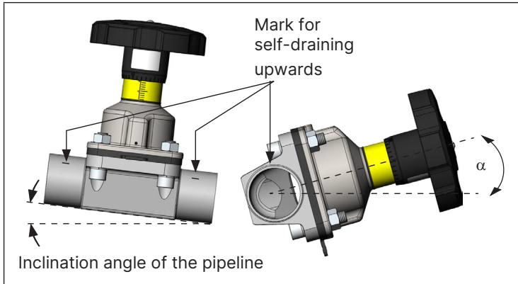
Installation position is any, preferably with the actuator facing up. To ensure self-draining, the self-draining angle (α) depends on the valve body size and the inner diameter of the port connection. The marking on the port connection of the valve body serves as an orientation aid and must point upwards.
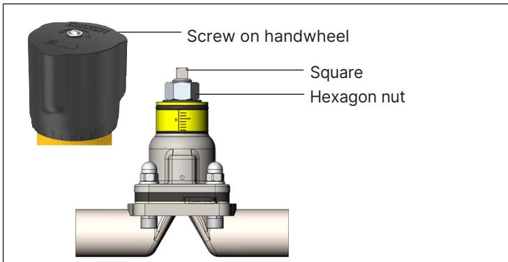
This setting also serves as a closing limiter to protect the diaphragm. A hexagon nut is used to do this.
TIP
After the first steam sterilisation, or when required, retighten the fastening screws crosswise.
The diaphragm is buttoned for diaphragm size 8.
Explore similar products in our catalog