PN16

BURKERT 353014 (Type 6213) servo-assisted 2/2-way diaphragm valve. Normally closed, brass body, G 1 1/2 internal thread, EPDM seal, 230-240V. Suitable for neutral media up to 90°C.
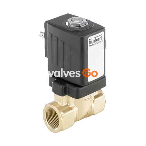
BURKERT 353014 (Type 6213) is a servo-assisted 2/2-way diaphragm valve. The spring coupling of the diaphragm supports the opening process in the valve. In its standard variant, the valve is suitable for deployment with liquids. A minimum differential pressure is required for full opening.
The valve features a brass body with a G 1 1/2 internal thread, an EPDM seal, and operates at 230-240 V (50/60 Hz). It is designed for a nominal pressure range of 0 to 10 bar and is suitable for neutral media with temperatures ranging from -30 °C to +90 °C.
| Product Properties | Details |
|---|---|
| Orifice | 40.00 mm (DN 40) |
| Circuit Function | A (Normally closed) |
| Body Material | Brass |
| Seal Material | EPDM |
| Coil Material | Polyamide, epoxy (insulation class H) |
| Duty Cycle | 100% continuous operation |
| Operating Voltage | 230-240 V, 50/60 Hz |
| Voltage Tolerance | ±10% |
| Nominal Pressure | 0 - 10 bar |
| Medium Temperature | -30 °C to +90 °C |
| Ambient Temperature | Max. +55 °C |
| Degree of Protection | IP65 with cable plug |
Circuit Function A (CF A): 2/2-way solenoid valve, servo-controlled, normally closed.
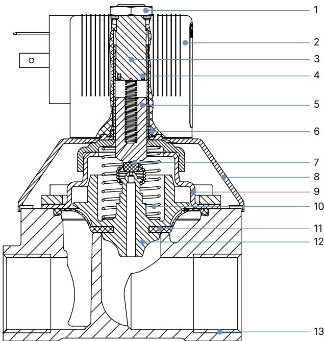
| No. | Element | Material |
|---|---|---|
| 1 | Nut | Steel (thick-film passivated according to RoHS), Stainless steel 1.4305, PTFE-coated |
| 2 | Coil | Polyamide or epoxy |
| 3 | Stopper | Stainless steel 1.4113 |
| 4 | Shading ring | Copper (Cu) for brass body |
| 5 | Magnetic core | Stainless steel 1.4113 |
| 6 | O-ring | FKM |
| 7 | Plunger seal | NBR, FKM, EPDM |
| 8 | Bonnet | PA6 |
| 9 | Cover | Brass, stainless steel 1.4408 (for DN 40) |
| 10 | Spring | Stainless steel 1.4310 |
| 11 | Diaphragm | NBR, FKM, EPDM |
| 12 | Diaphragm support | PPSGF40 in combination with brass |
| 13 | Valve body | Brass |
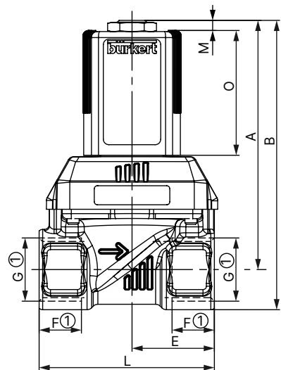
Dimensions in mm. The dimensions F1 and G1 apply to G thread.
| DN | A | B | C | D | E | F1 | G1 | L | SW | Coil Size |
|---|---|---|---|---|---|---|---|---|---|---|
| 40 | 159.4 | 189.4 | 104.5 | 117 | 61 | 22 | G 1 1/2 | 126 | 60 | K and L |
DANGER!
Risk of injury from high pressure in the system Before loosening lines or valves, switch off the pressure and vent the lines.
Risk of injury from electric shock Before reaching into the device or the system, switch off the power supply and secure it against reactivation. Observe the applicable accident prevention and safety regulations for electrical devices.
WARNING!
Risk of injury due to improper installation Installation must be carried out by authorised technicians only and with the appropriate tools. Secure the system against unintentional activation and ensure a controlled restart after installation.
Before Installation:
Installation:
NOTICE!
Breaking hazard Do not use the solenoid as a lever arm. Hold the device on the body using an open-end wrench and screw into the pipeline.
Explore similar products in our catalog