Up to 99.8% Efficiency

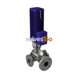
Burkert Type 2100 (SKU 464724) pneumatically operated 2/2-way angle seat valve. Features stainless steel body, NPT 3/4 connection, PTFE seal, and IP65/67 protection for decentralized automation.
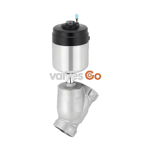
The BURKERT 464724 (Type 2100) pneumatically operated 2/2-way angle seat valve is specially optimised for decentralized process automation and fulfils the tough criteria in process environments. Its unique design allows easy integration of automation units in all expansion stages, from electrical/optical position feedback to pneumatic control and integrated fieldbus interface. Maximum service life and tightness are achieved by the proven self-adjusting V-seal packing gland. The highly integrated system of valve and automation unit is characterised by its compact and smooth design, integrated pilot air ducts, protection classes IP65/67, NEMA Type 4X, and high resistance to chemicals.

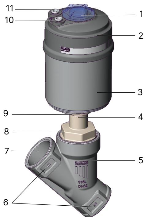
The type label provides essential information for safe operation, including the control function, flow coefficient, maximum medium temperature, and maximum operating pressure.

The closing force is transferred by a spindle connected to the actuator piston. The device uses neutral gases or air to control the flow rate of liquid or gaseous media.
Control Function A (CFA) The spring force generates the closing force on the swivel plate. The valve is normally closed by spring force in the rest position.
Control Function B (CFB) and I (CFI) The pilot pressure generates the closing force on the swivel plate. CFB is normally opened by spring force, while CFI has no defined rest position (double-acting).
Only use flow direction below the seat for liquid media, gases, and vapours. As the medium is present under the swivel plate, the operating pressure contributes to the opening of the valve.
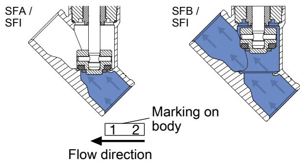
WARNING
Leaking valve seat with flow direction below seat If pilot pressure for control function B and control function I is too low or operating pressure is too high, this can cause the valve seat to leak. Comply with the minimum control pressure and the maximum operating pressure values.
Only use flow direction above the seat for gases and vapours, and for valves with control function A. As the medium is present above the swivel plate, the operating pressure contributes to the closing of the valve and supports the sealing of the valve seat.
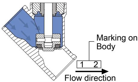
DANGER
Bursting lines and bursting device with flow direction above the seat In the case of liquid media, a pressure surge (water hammer) can lead to the bursting of lines and the device. Do not use valves with flow direction above the seat for liquid media.
| Component | Material |
|---|---|
| Actuator cover | PPS |
| Actuator casing | Stainless steel 1.4561 (316Ti) |
| Piston seal | FKM |
| Packing gland | PTFE V-Rings (filled), with spring compensation |
| Spindle | Stainless steel 1.4401 (316)/1.4404 (316L) |
| Spindle guide | PEEK |
| Swivel plate | Stainless steel 1.4401 (316)/1.4404 (316L) |
| Seat seal | PTFE, PEEK (Option) |
| Valve body | Stainless steel CF3M |
| Property | Value |
|---|---|
| Operating medium | Steam, water, neutral gases, alcohols, oils, fuels, hydraulic fluids, salt solutions, alkalis, organic solvents |
| Medium temperature | -10 °C to +185 °C (up to +230 °C for high-temp variant) |
| Ambient temperature | -10 °C to +100 °C |
| Viscosity | Max. 600 mm²/s |
| Control medium | Air, neutral gases |
| Degree of protection | IP65/67 (EN 60529/IEC 60529) |
| Installation position | As required, preferably with actuator in upright position |
DANGER
Explosion hazard due to electrostatic charging! If the device is used in a potentially explosive atmosphere (ATEX Zones 1/21 or 2/22), sudden discharge of electrostatically charged devices can cause an explosion.
WARNING
Medium under pressure Medium under pressure can seriously injure people. In the event of overpressure or pressure surges, the device or lines can burst. Before working on the device or system, switch off the pressure and vent or empty the lines.
Pneumatic Connection:
Explore similar products in our catalog