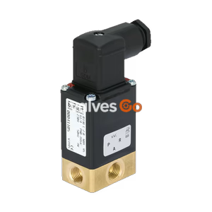
PN16

Burkert Type 8640 modular valve island (Model 710357) for pneumatics. Features a 33mm add-on dimension, 2-8 bar pressure range, DIN-rail mounting, and IP20 protection.
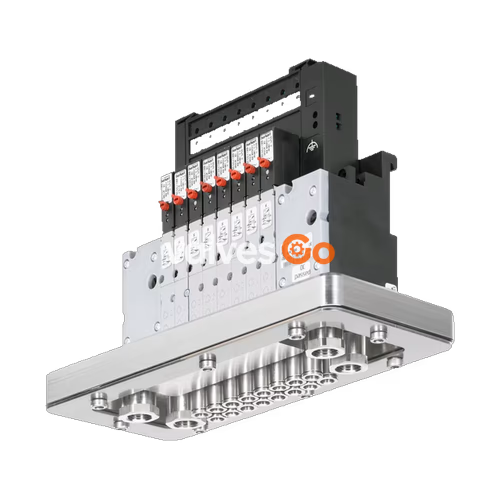
BURKERT 710357 Type 8640 modular valve island for pneumatics is designed to solve diverse and complex control problems due to its systematic modular construction and combination of pneumatic and electrical interfaces. By putting together a row of pneumatic modules with different numbers of valves, 2 to 24 valve functionalities may be realized on one valve unit. Electrical connectivity is achieved by either fieldbus interfaces, common connection (parallel connection technique) or multipin interfaces. The valves allow different applications to be covered. Bodies and connection modules are made of high-quality plastic (polyamide) and are easy to assemble by means of the built-in snap connectors.

| Module | Description |
|---|---|
| Collective connection module | Connection via individual stranded wires, looped-through ground potential, max. 24 valves, degree of protection IP20, screw-type terminals. |
| Multi-pin module Valve outputs | Max. 24 valves, degree of protection IP20, electrical connection plug D-Sub (2-pin). |
Available for PROFIBUS DP, PROFINET IO, EtherNet/IP, and Modbus TCP.
WARNING
Risk of injury due to high pressure and escaping medium. Switch off the pressure before working on the device or system. Vent or drain the pipes.
TIP
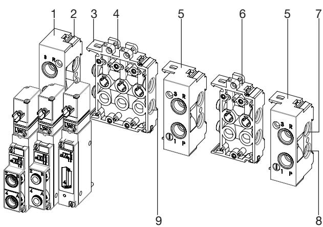
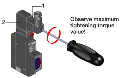
Crushed O-rings and profile seals lead to leaky blocks. Fasten each valve to the base module with 2 screws. Recommended tightening torque 0.6 ±0.1 Nm.
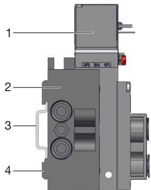
Standard rail installation:
Wall installation:
Observe the following tightening torques when screwing into the port connections. The specified tightening torque may vary depending on the sealing system.
| Port size | Marking/function | Recommended tightening torque [Nm] | Maximum tightening torque [Nm] |
|---|---|---|---|
| G1/4, NPT1/4 | P, R/S connection | 4...7 | 20 |
| G1/8, NPT1/8 | P, R/S connection A/B valve outlets | 3...6 | 7 |
| Fault | Possible cause | Remedy |
|---|---|---|
| Valves do not switch | No operating voltage or operating voltage too low | Check electrical connection. Ensure operating voltage according to type label. |
| Manual override not in zero position | Bring manual override to zero position. | |
| Pressure supply insufficient or not available | Set up large-volume pressure supply. Minimum operating pressure ≥ 2 bar. | |
| Valves switch with a delay or blow off at the exhaust ports | Pressure supply insufficient or not available | Set up large-volume pressure supply. Minimum operating pressure ≥ 2 bar. |
| Valves are not in the home position (de-energised) during pressure build-up | Apply pressure to the valve block before the valves are switched. | |
| Insufficient ventilation of the exhaust air ducts due to too small or dirty silencers | Use suitably sized silencers or expansion vessels. Clean the dirty silencers. | |
| Leaky valve blocks | Missing or crushed O-rings between the modules | Identify leak or missing seals. |
| Missing or incorrectly positioned flat seals between valve and base plate | Insert missing seals or replace damaged seals. |
Explore similar products in our catalog