
Linear Output
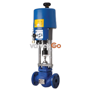
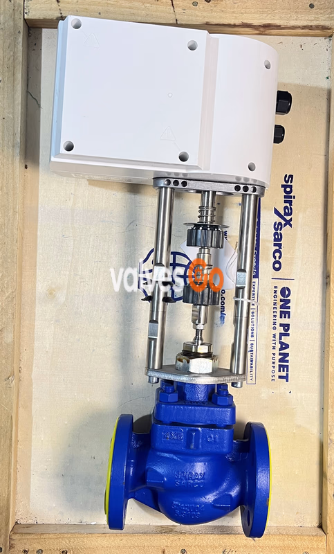
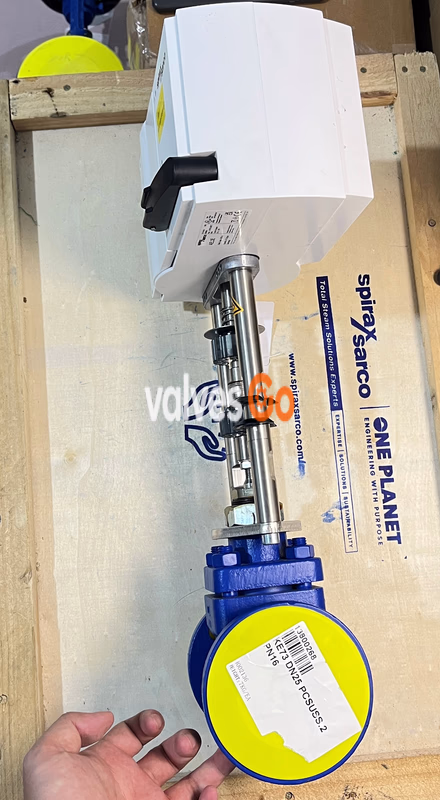
Spirax Sarco AEL3 Electric Linear Actuator, designed for Spira-trol two-way control valves and QL three-way valves, suitable for chilled water, hot water, steam or air systems, typically used in HVAC applications. Supports 24Vac/dc standard power supply with optional 230Vac or 100-110Vac power modules, accepts VMD, 4-20mA or 0-10Vdc control signals, features three speed adjustment options, IP66 protection rating, stable and reliable operation.
Spirax Sarco AEL3 Electric Linear Actuator is a stepper motor driven actuator specifically designed for Spira-trol series two-way control valves (DN15-DN50) and QL series three-way valves (DN15-DN50), enabling on/off control, modulating control, or special control functions. This product is suitable for chilled water, hot water, steam, or air media systems, with typical applications including HVAC systems and other industrial fluid control applications.
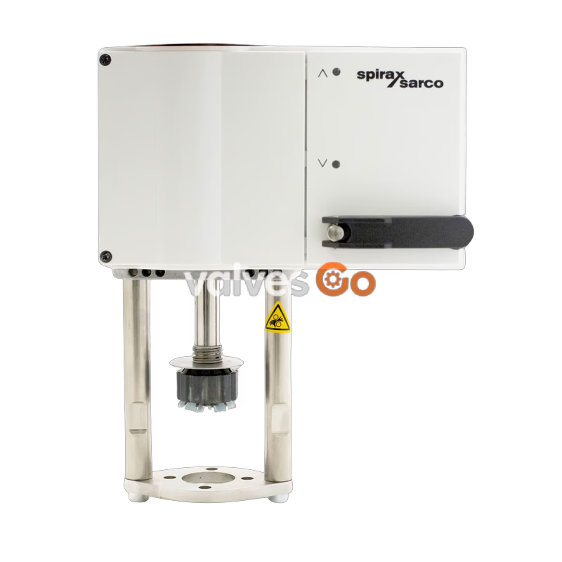
The actuator features a maintenance-free gearbox design with three fail-safe mode options: spring extend (AEL3E), spring retract (AEL3R), and non-spring (AEL3X) to meet different safety requirements. Standard power supply is 24Vac/dc, with optional 230Vac or 100-110Vac power modules available for specific applications. Control signals support VMD (Valve Motor Drive), 4-20mA analog signal, and 0-10Vdc analog signal; the 24Vac/dc version can also be expanded with a signal module for 2-10Vdc control. The actuator is equipped with three speed adjustment options, configurable via DIP switches to adapt to different response requirements.
| Parameter | Specification |
|---|---|
| Power Supply | Standard: 24Vac/dc (±15%); Optional: 230Vac, 100-110Vac (Requires Power Module) |
| Power Frequency | 50Hz/60Hz/Continuous |
| Power Consumption | 24Vac/dc: 12W; 230Vac/100-110Vac: 28VA |
| Control Signal | Standard: VMD, 4-20mA, 0-10Vdc; Extended: 2-10Vdc (24Vac/dc + Signal Module Only) |
| Feedback Signal | 0-10Vdc (Load >2500 ohms) |
| Actuator Speed | 0.5mm/s (2s/mm), 0.25mm/s (4s/mm), 0.16mm/s (6s/mm), DIP Switch Adjustable |
| Maximum Thrust | 2kN |
| Maximum Stroke | 20mm |
| Protection Rating | IP66 (EN60529) |
| Operating Temperature | -10℃~+55℃ |
| Storage Temperature | -20℃~+70℃ |
| Relative Humidity | <95% |
| Altitude | ≤2000m |
| Overvoltage Category | III |
| Pollution Degree | III |
| Spring Return Cycles | >40000 cycles |
| Status Indication | 2 LED lights (Status + Alarm) |
| Certification Type | Related Standards |
|---|---|
| EMC Directive | 2014/30/EU, EN61000-6-2, EN61000-6-4 |
| LV Directive | 2014/35/EU, EN60730-1, EN60730-2-14 |
| Other Certifications | UL-UL873, cUL-CSA-C22.2 No.24-93 (Note: Not applicable to auxiliary limit switches, signal modules, and 230VAC/100-110VAC power modules) |
| Actuator Model | Valve DN Size | PTFE Seat Max ΔP (bar) | Graphite Seat Max ΔP (bar) |
|---|---|---|---|
| AEL3E/AEL3R/AEL3X | DN15 | 40.0 | 40.0 |
| AEL3E/AEL3R/AEL3X | DN20 | 40.0 | 40.0 |
| AEL3E/AEL3R/AEL3X | DN25 | 39.1 | 31.2 |
| AEL3E/AEL3R/AEL3X | DN32 | 30.7 | 24.6 |
| AEL3E/AEL3R/AEL3X | DN40 | 11.5 | 8.8 |
| AEL3E/AEL3R/AEL3X | DN50 | 7.5 | 5.6 |
| Actuator Model | Valve DN Size | PTFE Seat Max ΔP (bar) | Graphite Seat Max ΔP (bar) |
|---|---|---|---|
| AEL3E/AEL3R/AEL3X | DN15 | 40.0 | 40.0 |
| AEL3E/AEL3R/AEL3X | DN20 | 40.0 | 40.0 |
| AEL3E/AEL3R/AEL3X | DN25 | 40.0 | 38.5 |
| AEL3E/AEL3R/AEL3X | DN32 | 35.5 | 29.4 |
| AEL3E/AEL3R/AEL3X | DN40 | 14.6 | 12.0 |
| AEL3E/AEL3R/AEL3X | DN50 | 10.2 | 8.3 |
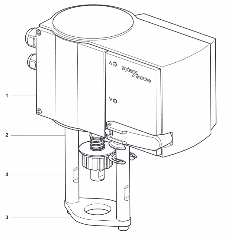
| Component | Material |
|---|---|
| Housing | Polycarbonate |
| Yoke | Stainless Steel |
| Mounting Flange | Stainless Steel |
| Adapter | Stainless Steel |
| Product Model/Component | Weight (kg) |
|---|---|
| AEL3E/AEL3R | 5.7 |
| AEL3X | 4.2 |
| 180℃ High Temp Kit | 0.4 |
| 240℃ High Temp Kit | 0.7 |
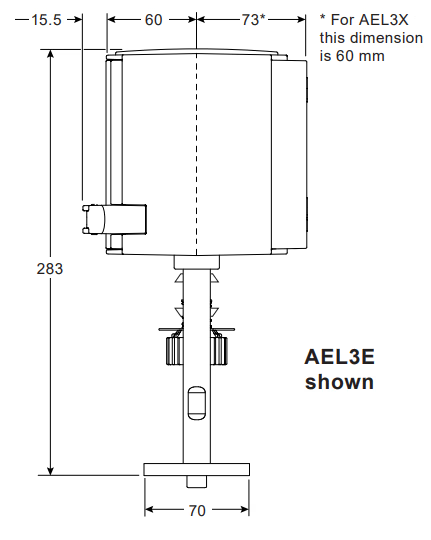
| Component | Dimension Details |
|---|---|
| AEL3E/AEL3R Length | 283 |
| AEL3X Length | 230 |
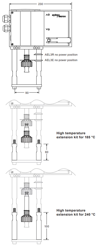
| High Temp Kit (180℃) Length | 60 |
| High Temp Kit (240℃) Length | 90 |
| Other Key Dimensions | 15.5, 60, 73, 70 (Refer to product drawings) |
Pre-Installation Notice
Wiring Standards
Installation Steps
Caution
This power module is not compatible with the 2-10V signal module.
Removal Steps
Installation Steps
Note
High temperature kits are available in two types: for 130℃~180℃ and 180℃~240℃ applications.
Installation Steps
Installation Steps
Commissioning Process
Commissioning Method
| LED Status | Indication |
|---|---|
| Both lights flashing red simultaneously | Commissioning in progress |
Maintenance Guidelines
Safety Warning
| Code | Description |
|---|---|
| A | Actuator |
| E | Electric Type |
| L | Linear Action |
| 3 | Series Number |
| Fail Mode | E=Spring Extend, R=Spring Retract, X=Non-Spring |
| Thrust | 2=2kN |
| Stroke | 20=20mm |
| Max Speed | 2s/mm=0.5mm/s, 4s/mm=0.25mm/s, 6s/mm=0.16mm/s (DIP Switch Adjustable) |
| Power | 24Vac/dc (Standard), 230Vac/100-110Vac (Requires Power Module) |
| Control Signal | 24-230V VMD, 0-10Vdc, 4-20mA; 2-10Vdc (Requires Signal Module, 24Vac/dc Only) |
Selection Recommendations
Examples
Explore similar products in our catalog