ENP Nickel Plating
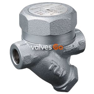
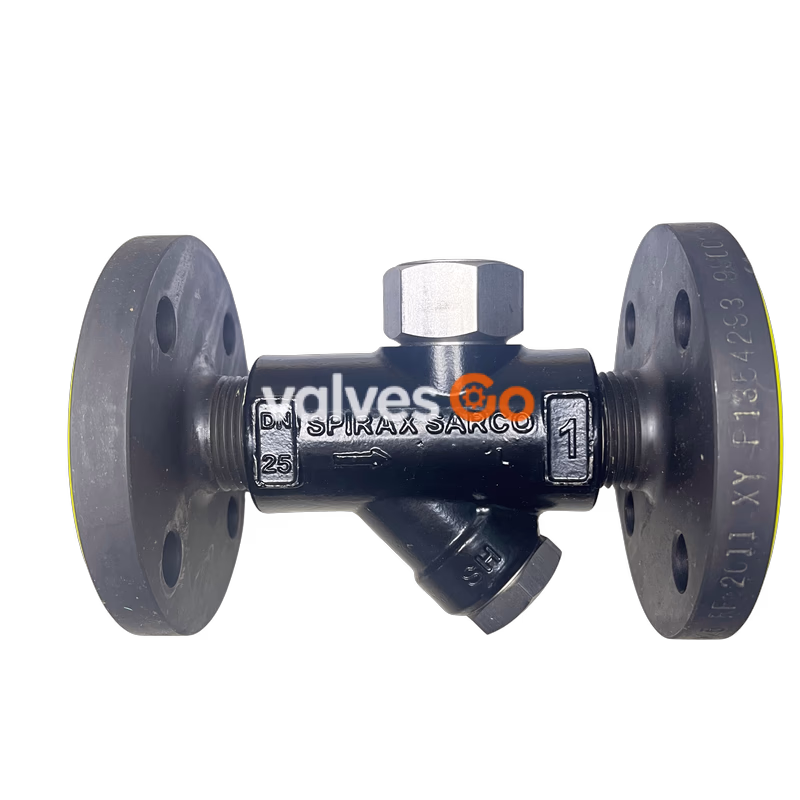
Spirax Sarco TD25 and TD25F Thermodynamic Steam Traps are designed for low capacity steam mains and tracer lines, suitable for various applications within specific pressure, temperature and capacity ranges. Maximum working pressure up to 25 bar g, manufactured with high-quality stainless steel, featuring reliable construction and low heat loss. Optional insulating hood effectively prevents excessive cycling, ensuring stable steam system operation.

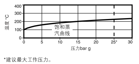
Spirax Sarco TD25 and TD25F Thermodynamic Steam Traps are specifically designed for low capacity steam mains and tracer lines, also suitable for other industrial applications within their specified pressure, temperature and capacity ranges. Maximum working pressure is 25 bar g, maximum allowable temperature reaches 400°C, capable of handling demanding industrial steam system conditions.
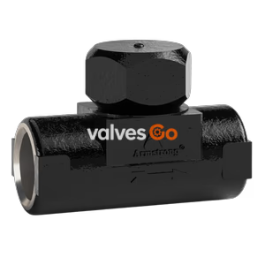
Optional insulating hood is available to effectively prevent excessive heat loss when the steam trap is exposed to cold environments or rain and wind, thereby preventing excessive cycling and improving equipment operational stability and service life.
| Design Parameter | Value |
|---|---|
| Max. Allowable Pressure (PMA) | 40 bar g |
| Max. Allowable Temperature (TMA) | 400°C |
| Max. Working Pressure on Saturated Steam (PMO) | 25 bar g |
| Max. Working Temperature (TMO) | 400°C |
| Max. Cold Hydraulic Test Pressure | 60 bar g |
Critical Operating Limitation
During operation, maximum working backpressure must not exceed 80% of inlet pressure, otherwise the steam trap will not close properly.
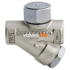
Supports DN15, DN20, DN25 three size specifications to meet different pipeline installation requirements.
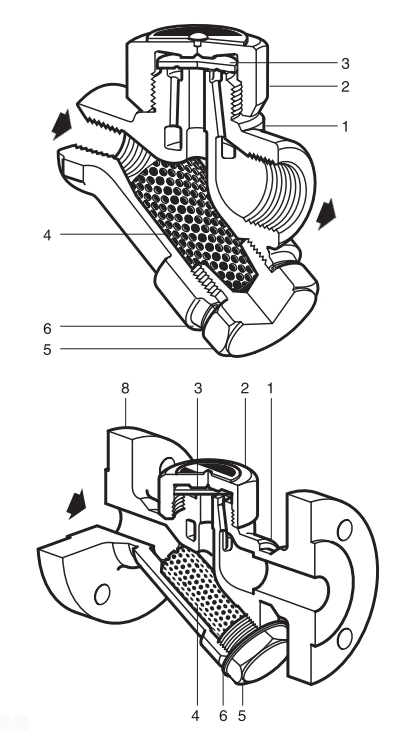
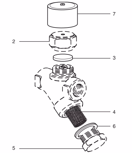
| No. | Part Name | Material Standard | Material |
|---|---|---|---|
| 1 | Body | ASTM A743 Gr.CA40F | Stainless Steel |
| 2 | Cap | AISI 416 | Stainless Steel |
| 3 | Disc | BS 1449 420 S45 | Stainless Steel |
| 4 | Strainer | BS 1449 304 S16 | Stainless Steel |
| 5 | Strainer Cap | AISI 416 | Stainless Steel |
| 6 | Strainer Cap Gasket | BS 1449 304 S16 | Stainless Steel |
| 7 | Insulating Hood (Optional) | - | Aluminium |
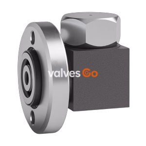
| 8 | Flange | - | Carbon Steel |
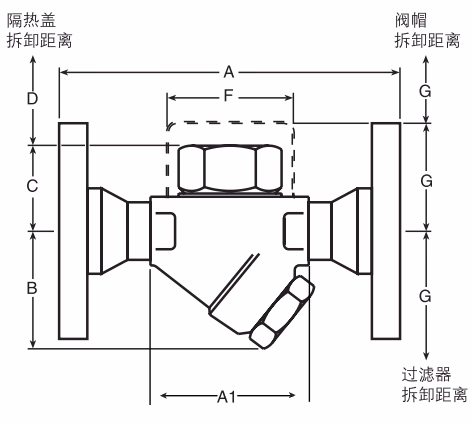
| Size | A1 | A | B | C | D | E | F | G | H | Weight-Flanged | Weight-Threaded |
|---|---|---|---|---|---|---|---|---|---|---|---|
| DN15 | 78 | 150 | 55 | 41 | 40 | 80 | 57 | 38 | 52 | 2.4 kg | 0.75 kg |
| DN20 | 85 | 150 | 60 | 44 | 40 | 100 | 57 | 38 | 52 | 3.1 kg | 0.95 kg |
| DN25 | 95 | 160 | 65 | 48 | 40 | 100 | 57 | 38 | 58 | 4.2 kg | 1.50 kg |
Note
Dimensions in mm, weights are approximate values, refer to actual product for installation.
Pressure Safety
Temperature Safety
| Part No. | Size | Tightening Torque (N·m) |
|---|---|---|
| 2 | 36 | 135-150 |
| 5 | 32 (M28) | 170-190 |
| Spare Part Name | Part No. | Notes |
|---|---|---|
| Disc (Set of 3) | 3 | Core sealing component |
| Strainer and Gasket | 4, 6 | Filter and sealing assembly |
| Insulating Hood | 7 | Optional accessory |
| Strainer Cap Gasket (Set of 3) | 6 | Sealing spare |
Note
Solid lines in diagram indicate available spare parts, dashed lines indicate parts not available as spares.
1-Spirax Sarco TD25 Thermodynamic Steam Trap, BSP Threaded Connection
This product can be recycled. Disposal according to standard procedures will not cause ecological problems and meets environmental requirements.
Spirax Sarco Thermodynamic Steam Traps
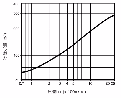
Spirax Sarco thermodynamic steam traps: design features, model range, technical specifications, and cold water capacities covering TD16 to TD120M.
Explore similar products in our catalog