


PN16

The TLV FS3 QuickTrap® is a universal free float steam trap for small to medium capacity applications up to 4.6 MPaG, featuring continuous discharge and thermostatic air venting.
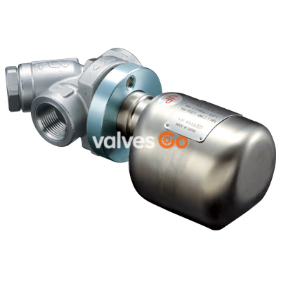
The TLV FS3 QuickTrap® is a universal free float steam trap with thermostatic air venting, designed for installation in any pipeline inclination. It is suitable for small and medium capacity applications between 0.01 and 4.6 MPaG (1 and 650 psig), such as saturated and superheated steam mains, branches, tracer lines, and small-to-medium size process equipment. The trap discharges condensate continuously and automatically at a temperature slightly lower than the saturation temperature.
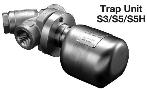
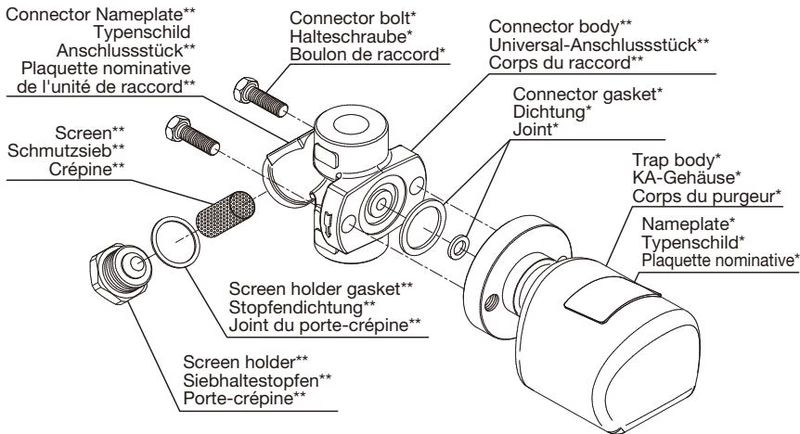
The QuickTrap® system consists of the S3 trap unit and a universal connector unit (F46 or the former F32). This two-part design facilitates rapid replacement and maintenance.
Float Explosion Hazard
NEVER apply direct heat to the float. The float may explode due to increased internal pressure, causing accidents leading to serious injury or damage to property and equipment.
Operating Limits
Install properly and DO NOT use this product outside the recommended operating pressure, temperature and other specification ranges. Improper use may result in damage to the product or malfunctions. DO NOT use this product in excess of the maximum operating pressure differential. Such use could make discharge impossible (blocked).
Refer to the product nameplates on the trap unit AND on the connector body for detailed specifications. The specifications displayed on each nameplate apply only to the unit on which it is mounted.
When the trap unit is installed on a connector unit and the PMA/TMA and/or PMO/TMO values displayed on the two nameplates differ, the specifications for the assembled product are restricted to the lower values.

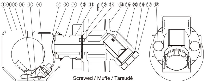
| No. | Description | No. | Description |
|---|---|---|---|
| 1 | Trap body | 7 | Connector Joint |
| 2 | Inner Cover | 8 | Trap Screen |
| 3 | Float | 9 | Nameplate (Trap Unit) |
| 4 | Orifice | 10 | Connector Flange |
| 5 | Float Guide | 11 | Snap Ring |
| 6 | Air Vent Strip |
Snap Ring Precaution
Do not remove the snap ring used to fix the connector flange.
Install the steam trap for use under conditions in which no freeze-up and no water hammer will occur. There are no restrictions on the installation direction beyond the following essential requirements:
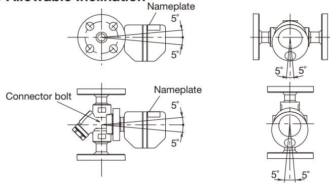
A visual inspection can be carried out to aid in determining the necessity for immediate maintenance or repair if the trap is open to the atmosphere.
| Status | Visual and Auditory Indication |
|---|---|
| Normal | Condensate is discharged continuously with flash steam and the sound of flow can be heard. If there is very little condensate, there is almost no sound of flow. |
| Blocked | No condensate is discharged. The trap is quiet and makes no noise, and the surface temperature of the trap is low. |
| Blowing | Live steam continually flows from the outlet and there is a continuous metallic sound. |
| Steam Leakage | Live steam is discharged through the trap outlet together with the condensate and there is a high-pitched sound. |




