Product Overview
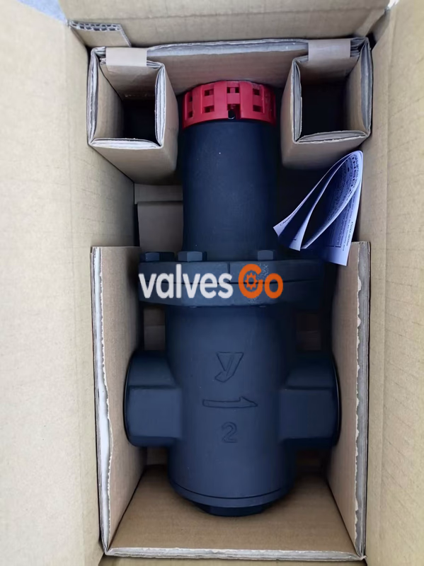
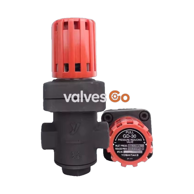
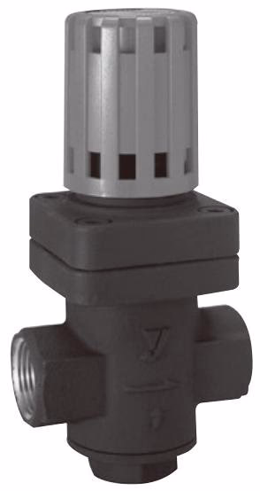
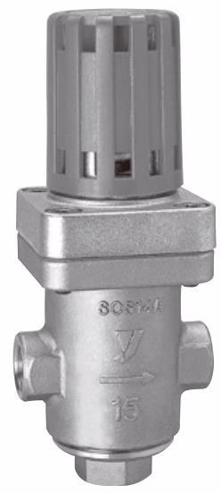
The Yoshitake GD-30/GD-30S Pressure Reducing Valve is a steam-dedicated pressure reducing device with direct-acting design, featuring the following key characteristics:
- Advanced design, compact and lightweight, simple structure with excellent durability and easy maintenance;
- JIS Rc threaded connection for simple and efficient installation without complex tools;
- Manual adjustment handle for direct pressure adjustment without additional tools;
- Stainless steel disc and seat combination ensures excellent wear resistance and long-term stability;
- Built-in 60 mesh strainer effectively filters debris from fluid, preventing disc and seat wear or blockage;
- External pressure bellows sensing element provides stable and reliable operation with high pressure control accuracy.
Technical Specifications
Basic Parameters
| Parameter | GD-30 Specification | GD-30S Specification |
|---|
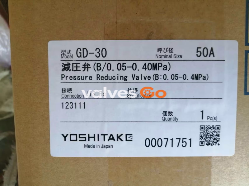
| Nominal Diameter | 15A-25A, 40A-50A | 15A-25A |
| Applicable Fluid | Steam | Steam |
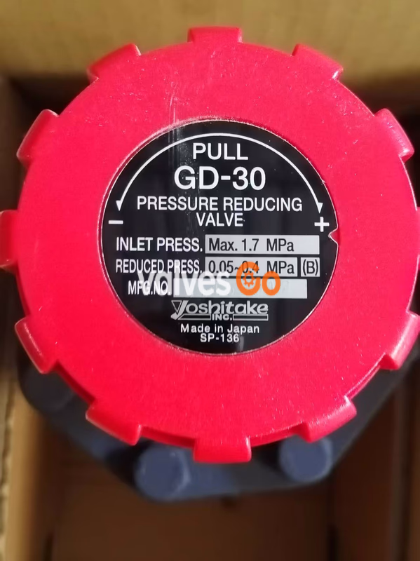
| Primary Pressure | 1.7 MPa max | 2.0 MPa max |
| Secondary Pressure Range | A Spring (Yellow): 0.02-0.1 MPa
B Spring (Blue): 0.05-0.4 MPa
C Spring (Yellow-Green): 0.35-1.0 MPa | Same as GD-30 |
| Min Differential Pressure | 0.05 MPa | 0.05 MPa |
| Max Pressure Ratio | 10:1 | 10:1 |
| Max Temperature | 210°C | 220°C |
| Seat Leakage | Less than 0.1% of rated flow | Less than 0.1% of rated flow |
| Connection Type | JIS Rc Threaded | JIS Rc Threaded |
Material Specifications
| Component | GD-30 Material | GD-30S Material |
|---|
| Body | Cast Bronze | Cast Stainless Steel (SCS14A) |
| Disc, Seat | Stainless Steel | Stainless Steel |
| Bellows | Phosphor Bronze | Stainless Steel |
Dimensions and Weight
GD-30 Dimensions and Weight
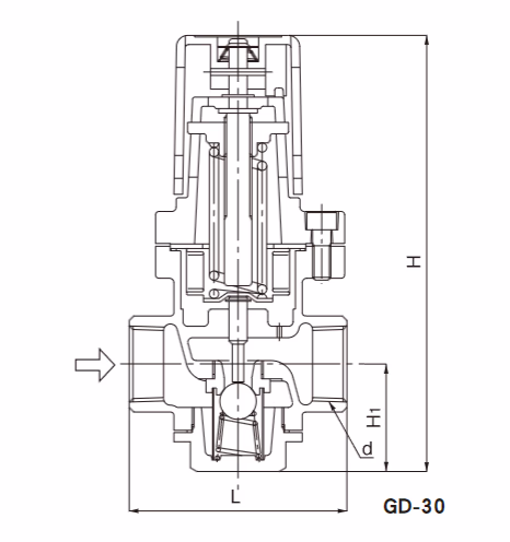
| Nominal Diameter | Connection (d) | Length (L) mm | Height (H) mm | Height (H1) mm | Weight (kg) |
|---|
| 15A | Rc 1/2 | 80 | 191 | 47 | 1.9 |
| 20A | Rc 3/4 | 85 | 191 | 47 | 1.9 |
| 25A | Rc 1 | 95 | 191 | 47 | 2.0 |
| 40A | Rc 1-1/2 | 140 | 307 | 77 | 10.1 |
| 50A | Rc 2 | 150 | 307 | 77 | 10.4 |
GD-30S Dimensions and Weight
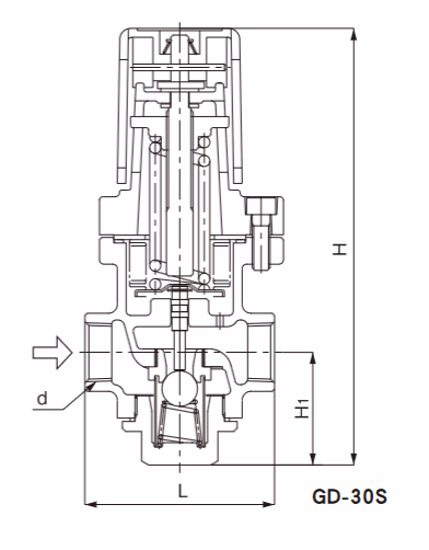
| Nominal Diameter | Connection (d) | Length (L) mm | Height (H) mm | Height (H1) mm | Weight (kg) |
|---|
| 15A | Rc 1/2 | 80 | 196 | 50.5 | 1.9 |
| 20A | Rc 3/4 | 85 | 196 | 50.5 | 1.9 |
| 25A | Rc 1 | 95 | 196 | 50.5 | 2.0 |
Note
GD-30S is only available in 15A-25A sizes
Operating Principle
The Yoshitake GD-30/GD-30S Pressure Reducing Valve achieves stable pressure control through the following principle:
- Rotating the adjustment screw connected to the handle compresses the adjustment spring, driving the disc open through the bellows and stem;
- Once the disc opens, secondary side steam acts on the bellows through the secondary pressure sensing port, creating an upward force opposite to the adjustment spring;
- The two forces balance each other, automatically adjusting valve opening to maintain secondary pressure at the set value;
- When secondary pressure exceeds the set value, the bellows moves upward, closing the disc; when secondary pressure falls below the set value, the adjustment spring pushes the disc open, achieving dynamic balance.
Component Structure
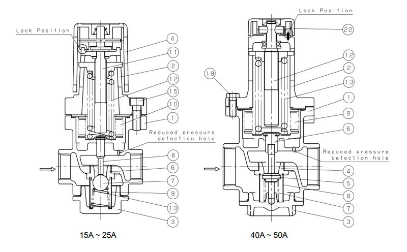
15A, 20A, 25A Model Components
| No. | Component Name | No. | Component Name |
|---|
| 1 | Body | 9 | Strainer |
| 2 | Protective Cover | 10 | Bellows |
| 3 | Bonnet | 11 | Adjustment Screw |
| 4 | Handle | 12 | Adjustment Spring |
| 6 | Seat | 13 | Disc Spring |
| 7 | Disc | 15 | Hexagon Socket Bolt |
| 8 | Stem | - | - |
40A, 50A Model Components
| No. | Component Name | No. | Component Name |
|---|
| 1 | Body | 8 | Strainer |
| 2 | Protective Cover | 9 | Bellows |
| 3 | Bonnet | 12 | Adjustment Screw |
| 22 | Handle | 13 | Adjustment Spring |
| 4 | Seat | 7 | Disc Spring |
| 5 | Disc | 19 | Hexagon Bolt |
| 6 | Stem | - | - |
Selection Guide
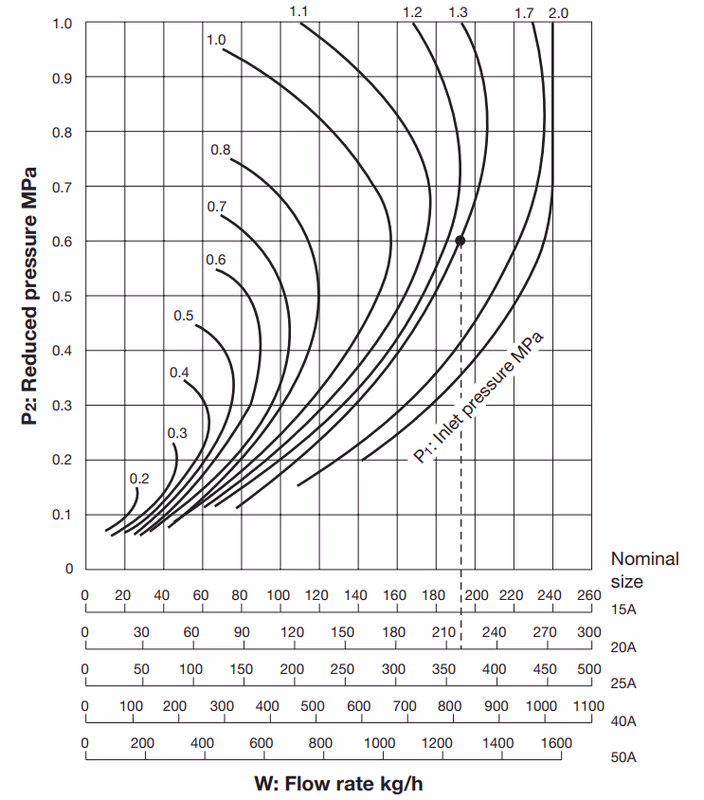
Nominal Diameter Selection Method
- Determine the primary pressure (P1), secondary pressure (P2), and steam flow rate (W) for your application;
- Find the intersection of P1 and P2 on the nominal diameter selection chart;
- Extend vertically downward from the intersection to find the nominal diameter corresponding to your flow rate or higher;
- Allow 80%~90% safety factor when selecting.
Selection Example
For primary pressure 1.3 MPa, secondary pressure 0.6 MPa, and steam flow rate 200 kg/h, the nominal diameter at the P1-P2 intersection vertically down to 200 kg/h flow rate is 20A.
Note
Selection chart is based on actual data calculations. Pressure differential and flow rate have no fixed correlation, so a fixed Cv value cannot be calculated.
Installation Instructions
Piping Requirements
The piping system should include in sequence: Stop Valve → Strainer → Separator → Steam Trap → Pressure Gauge → GD-30/30S Reducing Valve → Pressure Gauge → Safety Valve → Stop Valve → Steam Equipment. A bypass line and steam trap should also be installed.
Installation Warnings and Precautions
Warning
When installing a safety valve on the outlet side, a steam discharge pipe must be provided to direct steam to a safe area to prevent burns.
Precautions
- Do not disassemble the product arbitrarily, as this may cause malfunction;
- Remove debris and dirt from pipes before installation to avoid affecting product performance;
- An 80 mesh strainer must be installed on the inlet side to prevent debris from entering the valve body;
- A safety relief valve should be installed on the outlet side to detect product abnormalities promptly;
- Pressure gauges must be installed at both inlet and outlet to ensure accurate pressure adjustment;
- A steam trap must be installed upstream of the reducing valve to prevent condensate problems;
- Maintain ≥3 meters distance from quick-acting valves (such as solenoid valves) to avoid malfunction and shortened lifespan;
- For two-stage pressure reduction, maintain ≥3 meters between products;
- Install strictly according to inlet/outlet markings; incorrect direction will cause malfunction;
- Avoid applying load, bending, or vibration to the product during piping;
- Installation direction should be perpendicular to horizontal piping;
- A bypass line must be installed (refer to piping diagram);
- Safety relief valve set pressure should be higher than reducing valve adjustment pressure;
- For large pressure ratios, install reducers to control pipe flow velocity to 20~30 m/s.
Operation
Operation Warnings and Precautions
Warning
- Do not touch the product directly by hand during operation to avoid high-temperature burns;
- Before introducing steam, confirm that pipe connections are secure and there are no safety hazards at pipe ends.
Precautions
- Before starting, close stop valves before and after the product, clear debris through the bypass line, then slowly open each stop valve to avoid water hammer and vibration;
- Rotate the handle slowly when adjusting pressure to prevent water hammer damage to equipment;
- Before long-term shutdown, completely drain fluid from the product and piping, close stop valves before and after to prevent rust.
Pressure Adjustment Method
- Lift the handle upward to unlock;
- Rotate the handle clockwise to increase secondary pressure; rotate counterclockwise to decrease secondary pressure;
- Release the handle and it will automatically lock downward.
Special Adjustment (40A, 50A High Pressure Setting)
- Lift the handle upward to unlock;
- Insert a φ6 shaft diameter screwdriver fully into the slot on the side of the handle;
- Rotate the handle using the screwdriver to adjust pressure.
Precautions
- Control the rotation range of the handle to prevent the spring bracket from contacting the protective cover and causing damage;
- The handle may be hot; wear gloves during operation to prevent burns.
Maintenance
Troubleshooting
| Problem | Cause | Solution |
|---|
| Cannot reach set pressure | 1. Inappropriate operating pressure; 2. Nominal diameter too small; 3. Improper adjustment; 4. Inlet strainer clogged; 5. Built-in strainer clogged; 6. Pressure gauge malfunction | 1. Adjust to appropriate pressure; 2. Replace with suitable nominal diameter; 3. Re-adjust according to specifications; 4. Clean strainer; 5. Clean built-in strainer; 6. Replace pressure gauge |
| Secondary pressure exceeds specified value | 1. Debris caught in disc/seat or damage; 2. Outlet side pressure sensing port clogged; 3. Bypass stop valve leaking | 1. Disassemble and remove debris, replace parts if damaged; 2. Disassemble and clean sensing port; 3. Repair or replace bypass stop valve |
| Abnormal noise | 1. Pressure ratio too large; 2. Condensate problem; 3. Quick-acting valve nearby | 1. Use two-stage pressure reduction; 2. Install or check steam trap; 3. Increase distance from quick-acting valve |
Maintenance Inspection Precautions
Warning
Before disassembly inspection, internal pressure must be completely released and the product must be cooled. Do not touch or disassemble while pressurized or at high temperature.
Precautions
- Daily inspection should be performed by professional equipment installation personnel;
- Disassembly and inspection must be performed by professionals or the manufacturer;
- Use a container to catch condensate during disassembly; completely drain fluid before disassembling;
- Clear debris through the bypass line before starting to prevent debris from entering the valve body.
Disassembly and Assembly Method
- Confirm internal pressure is completely released and pressure gauge pointer is at 0;
- Lift the handle and rotate in the "-" direction (counterclockwise) as indicated on the nameplate to release the adjustment spring to its natural state;
- Remove the hexagon socket bolts (or hexagon bolts), remove the protective cover (handle cannot be disassembled), remove the adjustment spring, bellows, and stem;
- Remove the bonnet counterclockwise, remove the disc spring, strainer, and disc;
- Assemble in reverse order of disassembly; when installing the protective cover, tighten hexagon bolts evenly and ensure gaskets and bellows are installed correctly.
Consumable Parts
Internal components are provided as consumable parts. Contact the manufacturer for compatible replacement parts when needed.
After-Sales Service
- Warranty Coverage: Free repair for product abnormalities caused by material or manufacturing defects;
- Warranty Period: 1 year after delivery to user for trial operation, or 24 months after shipment (whichever comes first);
- Parts Supply After Discontinuation: Parts supply continues for 5 years after product discontinuation (except for individual contracts);
- Paid Repair Cases: Failures caused by piping debris, improper operation, abnormal water pressure/quality, scale or freezing, power/air supply issues, improper modification, harsh environment use, natural disaster damage, and consumable parts replacement require paid repair.
Note
Warranty coverage applies only to the product itself and does not include other losses caused by product failure.